10.26
Project Descriptions
Spring, 2002
Faculty
No. Title Advisor
1 Scaling Up Monoclonal Antibody in Novel and Traditional Bioreactors JFH
2 A Novel Fluidized-Bed Perfusion Bioreactor for Antibody Production JFH
3 Integration of Bioreactor with Novel Centrifuge for Improving Process JFH
Performance
4 Development of Process Control Loops for Operation of a Mammalian Cell JFH
Bioreactor for Protein Production
5 Performance Testing of a Proton-Exchange Membrane (PEM) Fuel Cell JM
6 Characterization of a Palladium-based Membrane Purifier for Production JM
of Fuel-Cell-Quality Hydrogen
7 Characterization of a H2-Selective Membrane System for Production of JM
Fuel-Cell-Quality Hydrogen
8 Mass Transport of Bioactive Molecules from Arterial Stents BSJ
9 Evaluation of New Instrument to Measure Swelling in Polymers BSJ
10 Reduction of Purge Time for an Airlock WHD
11 Heat and Mass Transfer during Cooking of Mashed Potatoes WHD/CKC
12 Enhancement of Dialysis with Ultrasonic Energy WHD/CKC
13 Hydrogen Storage on Carbon Nanostructures JBH
14 Separation of Fullerenes by Fractional Crystallization JBH
15 Modelling of Drag Reduction by Polymers in Crude Oil Pipelines: PSV
1. Effect of Injection and Mixing of the Polymeric Additive
16 Modelling of Drag Reduction by Polymers in Crude Oil Pipelines: PSV
2. Effect of Polymer Degradation on Drag Reduction
Massachusetts Institute of Technology
Department of Chemical
Engineering
Chemical Engineering Laboratory, Course 10.26
Spring 2002
Project
title: Scaling up Monoclonal Antibody in Novel
and Traditional Bioreactors
Project
location: Lab 13-3095
Sponsored
by: DasGip mbH (http://www.dasgip.de/),
Division of Bioengineering (BEH) and Biotechnology Process Engineering Center
(BPEC)
Consultants: Jose Manny Otero Mansour Sindi
Lab 16-436, ext. 3-2765 Lab 16-436, ext. 3-2765
E-mail: manny1@mit.edu E-mail: msindi@mediaone.net
Faculty
advisor: Jean-François Hamel
Office
56-483, ext. 8-6665
E-mail: jhamel@mit.edu
![]()
Objective
To
demonstrate: 1) the equivalency of CellFerm-Pro®
with traditional stirred-tank reactors for cell culture process development
and, 2) the scale-up ability of over two orders of magnitude.
In this project, students will:
·
Learn general techniques and processes relevant to a
career in the biotechnology and pharmaceutical industries.
·
Learn analytical techniques, such as cell counting and
lab-on-a chip technology.
·
Use aseptic techniques for maintaining a pure culture
in a bioreactor for several days.
·
Learn the operation of state-of-the-art
process-controlled bioreactors. Dr. Rix from DasGip will come from Gerrmany,
especially to give a lecture on the CellFerm-Pro®
to the students.
Desired
Student Team Background
1. Microbiology,
fermentation engineering or cell culture techniques; course 7.02 or equivalent.
3. Analytical techniques
in protein and antibody analysis (e.g. gel electrophoresis).
Project
Background
At
the industrial scale, hybridoma cells have become
standard cell lines for production of monoclonal antibodies. Bioprocess
development of hybridoma cell culture is dependent on
the ability to optimize a culture system at relatively small volumes, in a
short period, and cost-effectively. Traditional small-volume vessels may
include T-flasks, spinner flasks, roller bottles, shaker flasks, or other
conventional bioreactors that are simple to operate. However, these bioreactors
do not lend themselves to optimization of pH, dissolved oxygen levels,
temperature levels, or agitation.
Typically, optimization studies conducted as part of a process
development and scale up are done in liter-size fermentors.
Their operation is time consuming and costly in terms of cell culture medium.
New technologies, such as offered by the CellFerm-Pro®,
offer the potential to carry out optimization studies more efficiently in a
multi-vessel system using 10 times less cell culture medium per vessel (as low
as 50 mL). As a result, if equivalency of data
generated by the CellFerm-Pro® and
traditional STRs can be shown, the CellFerm-Pro® could quickly become the workhorse
standard for conducting optimization of cell culture processes, and as a result
could serve as the starting point for scaling up industrial processes.
Massachusetts Institute of Technology
Department of Chemical
Engineering
Chemical Engineering Laboratory, Course 10.26
Spring 2002
Project
title: A Novel Fluidized-Bed Perfusion
Bioreactor for Antibody Production
Project
location: Lab 56-454
Sponsored
by: Amersham Biosciences (http://bioprocess.apbiotech.com/),
and Biotechnology Process Engineering Center (BPEC)
Consultant: Rudolph Czirbik
Ph:
800-526-3593
Fax:
(732) 457-8301
E-mail: mailto:rudolf.czirbik@am.amershambiosciences.com
Faculty
advisor: Jean-François Hamel
Office
56-483, ext. 8-6665
E-mail: jhamel@mit.edu
![]()
Objective
This
project will study the antibody (Ab) production of hybridoma cells in a novel CytopilotÒ fluidized-bed bioreactor.
The study will be conducted through the analysis of key parameters including
glucose levels, medium composition, waste product concentration and antibody
titer.
In this project, students will:
·
Learn general techniques and processes relevant to a
career in the biotechnology and pharmaceutical industries.
·
Learn analytical techniques, such as cell counting and
lab-on-a chip technology.
·
Use aseptic techniques for maintaining a pure culture
in a bioreactor for several days.
·
Learn the operation of state-of-the-art
process-controlled bioreactors.
Desired Student Team Background
1. Microbiology, fermentation
engineering or cell culture techniques.
2. Course 7.02 or equivalent.
3. Analytical techniques
in protein and antibody analysis (e.g. gel electrophoresis).
Project
Background
Hybridoma cells are the product of fusing myeloma cells and B-lymphocytes, the latter being isolated from a host organism. The exposure of the host to the target antigen results in the B-lymphocytes raising Ab against the antigen. Myeloma cells are cancer cells, hence they reproduce indefinitely. Thus hybridoma cells produce the desired antibodies and grow indefinitely.
The
CytopilotÒ is a
laboratory scale fluidized-bed reactor for cell culture,designed
for continuous operation as a perfusion system, i.e. fresh medium is added at
the same rate as the spent medium is removed. In the CytopilotÒ, hybridoma cells
attach to and grow in the core of the microcarriers.
The microcarriers protect cells from shear forces in
the fluidized bed, while allowing nutrients to reach the cells through the
pores. The fluidized bed allows circulation of O2 and nutrients
throughout the column. Hybridoma cells produce and
release the antibodies into the supernatant.
Massachusetts Institute of Technology
Department of Chemical Engineering
Chemical Engineering Laboratory, Course 10.26
Spring 2002
Project title: Integration of
Bioreactor with Novel Centrifuge for improving Process Performance
Project location: Lab 16-436
Sponsored by: Kendro Lab Products and
Consultant: Rick Bradley
Ph: (800) 522-7746
E-mail:
bradlerd@kendro.com
Faculty advisor: Jean-François Hamel
Office 56-483, ext. 8-6665
E-mail: jhamel@mit.edu
![]()
Objective
This
project will aim to: 1) study the effect of integrating a novel centrifuge with
a stirred-tank bioreactor on process performance, and 2) assess the potential
of the centrifuge to separate dead and live cells and to recycle the live cells
back to the bioreactor. This work will be conducted through the analysis of key
parameters including glucose levels, medium composition, cell concentration,
cell viability, waste product concentration and antibody titer.
In this project, students will:
·
Learn general techniques and processes relevant to a
career in the biotechnology and pharmaceutical industries.
·
Learn analytical techniques, such as cell counting and
lab-on-a chip technology.
·
Use aseptic techniques for maintaining a pure culture
in a bioreactor for several days.
·
Learn the operation of state-of-the-art
process-controlled bioreactor and centrifuge.
Desired Student Team Background
1. Microbiology,
fermentation engineering or cell culture techniques.
2. Course 7.02 or equivalent.
3. Analytical techniques
in protein and antibody analysis (e.g. gel electrophoresis).
Background
A
major component of the process for making monoclonal antibodies by cell culture
is the ability to produce gram quantities of product using a robust and simple
process. The commercial importance of monoclonal antibodies for diagnostic or
therapeutic applications has fueled the demand for their efficient production.
The Kendro Company has recently introduced the Centritech centrifuge which can be coupled with a
bioreactor for continuous operation of a bioreactor in the perfusion mode, in
which fresh medium is fed to the bioreactor at the same rate as spent medium is
removed. This study will produce data to determine the performance and the
economy of the perfusion system and assess the feasibility of removing dead
cells from the bioreactor selectively.
Massachusetts Institute of Technology
Department of Chemical Engineering
Chemical Engineering
Laboratory, Course 10.26
Spring 2002
Project
Title: Development of
Process Control Loops for Operation of a Mammalian Cell Bioreactor for Protein
Production
Project Location: Undergraduate
Chemical Engineering Lab
Biotechnology
Section
Sponsored
By:
Consultant: Jose M. Otero
(Manny)
Lab 16-436,
ext. 3-2165
E-mail: manny1@mit.edu
Faculty Advisor: Jean-François
Hamel
Office 56-483,
ext. 8-6665
E-mail: jhamel@mit.edu
![]()
Objective
To
develop a process control strategy for fed-batch culture of animal cells.
In this project, students will:
·
Learn how to design and implement a process control
scheme for maintaining parameters (e.g. glucose concentration) in a bioreactor.
·
Learn techniques relevant to a career in the
biotechnology and pharmaceutical industries.
·
Learn the operation of a state-of-the-art
process-controlled bioreactor.
Desired
Student Team Background and Support
·
Prior knowledge of process
control would be helpful. Expert consultants from PID Control Systems and
Honeywell will be available and provide necessary background.
·
No prior knowledge of cell
culture is needed.
Project
Background
Bioreactors have long been used to develop
and produce therapeutic and diagnostic agents serving many purposes, from
combating infectious disease to facilitating analytical chemistry
techniques. Critical to operation of
modern day bioreactors, which may vary in scale from 1 L to 10,000 L, is the ability
to provide automated control for process variables including temperature,
dissolved oxygen, pH, foam level control, and glucose/lactate
concentrations. For example, glucose is
often used as the control parameter in fed-batch techniques for achieving
high-cell density cultures while minimizing toxic lactate production. Control
modules such as the proportional-integral-derivative (PID) control can be very
effective in maintaining glucose to a low level (<1 g/L) through the feeding
of a concentrated solution of glucose.
The
elements of PID control may be better understood by evaluating each component
individually. The control unit provided
by Honeywell for this project has been interfaced to a computer and can easily
be programmed. The bioreactor available for the project is a state-of-the-art
stirred-tank reactor.
Project 5
10.26
Chemical Engineering Project Laboratory
Spring
2002
Performance Testing of a Proton-Exchange Membrane (PEM) Fuel Cell
Faculty Advisor: Industrial
Consultant
Dr. Jerry Meldon K.M. Abraham
Room 66-260 Chief Technology Officer
Tel: 617 452-3460 E-KEM Sciences
Jerry.Meldon@tufts.edu
Tel: 781-444-8453
Fax 781 455-6899
Ekemtec@aol.com
Goal
Determination of performance characteristics of a PEM fuel cell.
Background
Fuel cells generate electric power with higher thermodynamic efficiency and less environmental impact than conventional fossil-fuel-fired power plants. It is anticipated that the first fuel cell modules to capture a significant shares of the markets for stationary (home, industry, etc.) and/or mobile (vehicular) power sources will be low-temperature (<100oC) systems based on polymeric cation-exchange membranes (generally referred to as Proton-Exchange or PolyElectrolyte Membranes, PEMs). Such membranes consist of an organic polymer matrix with negatively charged sulfonate side groups, which is sandwiched between porous electrodes. The immobilized negative charge makes the membranes almost exclusively permeable to neutral molecules like water and cations like hydrogen ions. The cathode is exposed to humidified gas containing hydrogen, the anode to humidified oxygen or air. The overall chemical reaction is simply H2 + ½ O2 = H2O.
Our goal in this project is to characterize the performance of a PEM fuel cell.
Approach
· The open literature contains extensive information on fuel cell technology. The recent monograph, Fuel Cells Explained, by J. Larminie and A. Dicks, provides an excellent, lucid introduction to the field A website which provides useful links is: http://chemengineer.about.com/cs/fuelcells1/index.htm
Search the literature for basic information on fuel cells and specifics on the design and operation of PEM fuel cells.
· Develop a preliminary design of a small bench-scale system, based on your own simplified theoretical model and mathematical analysis, keeping in mind the data you will be obtaining (see below) and the availability of advice from the industrial consultant. The apparatus will be centered on a fuel cell along the lines shown in the figure. Determine whether an inexpensive system, or at least parts of one, is commercially available. If not, determine the cost of assembling your own. Verify that necessary ancillary equipment such as a multimeter is available for use.
· After deciding upon and securing the necessary parts, assemble the system and perform preliminary shakedown tests.
· Design and execute an experimental program to characterize the performance of the fuel cell in terms of current and power densities, efficiency and constancy of performance (in the short term) as functions of gas flowrates, use of pure oxygen vs. air and , if feasible, temperature and pressures.
Project xx
10.26
Chemical Engineering Project Laboratory
Spring
2002
Design and Characterization of a Reactor that Produces Hydrogen for Fuel Cells
Faculty Advisor: Industrial
Consultant
Dr. Jerry Meldon Dr. Charles Kruger
Room 66-260 WJA Inc.
Voice Mailbox
Tel:
617 627-2338
Goal
Identification of optimal conditions for operating a catalytic reactor to produce hydrogen for fuel cells via steam reforming of methanol, ethanol or both.
Background
Fuel cells generate electric power with considerably higher thermodynamic efficiency and less environmental impact than conventional fossil-fuel-fired power plants. It is anticipated that the fuel cell design which will be the first to capture a significant share of the markets for stationary (home, industry, etc.) and/or mobile (vehicular) power sources are “low-temperature” (<100oC) systems based on polymeric cation-exchange membranes. The latter membranes, which are permeable to hydrogen ions (protons) but impermeable to anions, are sandwiched between porous electrodes. The cathode is exposed to hydrogen, the anode to oxygen. See Projects xxx and xxxx for further details.
The primary obstacle to large-scale commercialization of fuel cells is cost. Size is also a major concern, particularly in vehicular applications. A third issue is the source of hydrogen. Not only is there currently no nationwide hydrogen distribution network, there is public resistance to the idea of handling and/or storage of pressurized hydrogen. The most attractive alternative is to generate hydrogen on demand from sources the public will accept..
The most promising such sources, for which there is extensive technical know-how, are mixtures of steam plus a hydrocarbon(s) [e.g, coal, and components of natural gas (methane) and oil]. When any of these mixtures are fed to a suitably designed catalytic reactor, hydrogen is formed via steam reforming of the hydrocarbon.
This project focuses on hydrogen production from mixtures of steam plus methanol and/or ethanol, for which the reforming reactions are:
CH3OH
+ H2O = CO2 + 3H2
C2H5OH
+ 3H2O = 2CO2 + 6H2
There is at least one side reaction, the (reverse) water-gas-shift (WGS):
CO2
+ H2 = CO + H2O
There is substantial interest in using either alcohol as a hydrogen source because of the relative safety, comparatively low reforming temperature, and potential use of biomass (e.g., agricultural and forestry waste products) as a feedstock for fermentation-based alcohol production. Note that the use of biomass minimizes the buildup of atmospheric CO2.
Our goal in this project is to use a bench-scale reactor to carry out an experimental investigation of catalytic steam reforming of one or both these alcohols, and thereby provide reliable data to engineers engaged in large-scale hydrogen production for fuel cells.
Approach
1) The open literature contains extensive data on the performance of various catalysts in steam reforming of each alcohol, as well as data on the WGS reaction and the potential for catalyst coking and/or poisoning. Search the recent literature (1980-present), summarize your findings, determine the availability of desired catalyts, and make recommendations regarding choice of alcohol(s), catalyst(s) and ranges of operating conditions (type of reactor, temperature, pressure, space velocity, etc.) to investigate experimentally
2) Design and construct a reactor to produce sufficient hydrogen to operate a low wattage fuel cell (the industrial consultant will provide guidance with respect to wattage and reactor design and construction).
3) Design and execute an experimental program to obtain data that will make possible the rational choice of operating conditions for a pilot-plant-scale reactor.
Project 7
10.26
Chemical Engineering Project Laboratory
Spring
2002
Characterization of a H2-Selective Membrane System for Production of Fuel-Cell-Quality Hydrogen
Faculty Advisor: Industrial
Consultant
Dr. Jerry Meldon Dr. Walter Juda
Room 66-260 WJA Inc.
Tel:
Jerry.Meldon@tufts.edu
Tel: 617 627-2786
Goal
Identification of optimal conditions for operating a membrane-based hydrogen purification system to produce fuel-cell-quality hydrogen from reformates of methanol and/or ethanol.
Background
Fuel cells generate electric power with higher thermodynamic efficiency and less environmental impact than conventional fossil-fuel-fired power plants. It is anticipated that the first fuel cell modules to capture a significant share of the markets for stationary (home, industry, etc.) and/or mobile (vehicular) power sources will be low-temperature (<100oC) systems based on polymeric cation-exchange membranes (generally referred to as proton-exchange membranes, PEMs). The membranes, which are permeable to hydrogen ions but impermeable to anions, are sandwiched between porous electrodes. The cathode is exposed to hydrogen, the anode to oxygen.
A major concern with PEM fuel cells is that the platinum cathodes are poisoned by (suffer reductions in activity in the presence of) carbon monoxide at concentrations significantly above 10 ppm. The preferred method of manufacturing hydrogen is via steam reforming of hydrocarbons [e.g, coal, and components of natural gas (methane) and oil]. Carbon monoxide is a byproduct in concentrations orders of magnitude above10 ppm.
Commercially available technology to purify hydrogen to fuel cell quality, involves a series of additional reactors, in the last of which CO (and some H2) is oxidized. The cost and, particularly in vehicular applications, the space required for this equipment are major obstacles to large-scale commercialization.
Permselective membrane systems offer an intriguing, simple alternative for purifying hydrogen. Foils of dense palladium and its alloys are semipermeable membranes: they are permeable only to hydrogen. Thus, it is possible to recover ultrapure hydrogen from mixtures, including those containing carbon monoxide - provided that operating conditions are chosen to minimize CO poisoning of the membranes.
This project focuses on hydrogen recovery from simulated reformate mixtures, i.e., the products from steam reformers. We will focus on reformates produced from methanol and ethanol, two hydrocarbons which can be produced via, among other routes, the fermentation of biomass. The reforming reactions are:
CH3OH + H2O = CO2 + 3H2
C2H5OH + 3H2O = 2CO2 + 6H2
A side reaction is the (reverse) water-gas-shift (WGS):
CO2 + H2 = CO + H2O
Generally, stream is fed in excess, and alcohol consumption is complete. Thus, the reformate fed to the membrane system (see figure below) will contain H2, CO, CO2 and H2O.
Our goal in this project is to
determine the feasibility of using a commercially available Pd-alloy membrane
hydrogen purifier (WJA Inc.,
Approach
1) The open literature contains extensive information on the permeability of hydrogen in palladium and Pd-alloy membranes. Collect information on the dependence on hydrogen permeation on temperature, feed and permeate pressures, membrane thickness and feed composition. Develop a simple algorithm for predicting hydrogen permeation rates. Use this plus product information provided by the industrial consultant to select operating conditions for the experimental study.
2) Design and construct an experimental system to test the WJA membrane module. The system should include provision of pressurized reformate; monitor feed and permeate flowrates; allow for sampling of the permeate for analytical purposes; and pressure control.
3) Design and execute an experimental study to (i) test the reliability of the algorithm, (ii) explore the extent, if any, to which CO reduces hydrogen permeability, and (iii) identify ranges of operating conditions for optimal hydrogen recovery.
Project
8
10.26 Chemical Engineering Projects Laboratory
Spring 2002
Project Description DRAFT
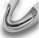
Project: Mass transport of bioactive molecules from arterial stents
Sponsor: Guidant Corporation Winnette McIntosh Syed Hossainy
www.guidant.com fax (408) 845-3685
Instructor: B. S. Johnston, 66-371, 87141, bsjohnst@mit.edu
Abstract
This project is about product performance; you will attempt to characterize the loss of bioactive molecules from arterial inserts to the bloodstream. The issues are (1) quantifying the rate of loss, (2) modeling diffusion and convection in the downstream flow, and (3) testing the sensitivity to several variables. If you succeed, you will aid Guidant in improving a useful medical product.
This project demands good lab skills and an understanding of transport phenomena in liquids. You will learn something about fluid mechanics, mass transfer, and a developing area of medical technology. Of course, you will improve your understanding and technique of experiments, as well.
Background
Partial blockage of arteries can sometimes be alleviated without surgery by inserting a balloon catheter into the artery. Inflating the balloon presses the arterial plaque to the wall and improves blood flow. To protect the artery from rebound of the plaque, a support device is sometimes inserted; it is called a stent. Stents are made of metal mesh in a variety of configurations; more information is available from Guidant (2002).
Because the stent is a foreign object, the artery may exhibit an injury response in the region of the stent. This reaction may be suppressed by local application of drugs. Stents may be coated with bioactive molecules before insertion into the artery. In time, these molecules leave the stent and diffuse into the abluminal endothelial cells that line the artery.
Only a fraction of the drug is made available to the artery, however, because some of it diffuses into the bloodstream instead. Guidant would like to understand the loss from the stent, as well as the downstream behavior of the drug in the bloodstream.
Objective
Quantify the mass transfer of a simulated bioactive molecule from a stent into a pulsatile flow.
Suggested Procedure
Review your mass transfer: models for diffusion and convection in liquids. What is the effect of pulsing flow?
Set up the apparatus. A peristaltic pump will deliver a pulsing flow through a clear tube. Stents, coated with dye molecules, will be inserted into the flow. Use UV spectrophotometry to measure the concentration of dye as a function of time and position in the downstream flow.
Plan your test procedure. Guidant will supply stents with two types of dye – hydrophilic and hydrophobic. You can vary the average flow rate, and the amplitude and frequency of the pulsing. Choose conditions that are appropriate to the artery and cover a suitable domain.
Refine both your apparatus and your model. Execute your tests and determine model parameters.
In the end, deliver to Guidant the means to predict dye concentration as a function of time and position.
Reference
Guidant,
http://www.guidant.com/products/stents.shtml (
Project
9
10.26 Chemical Engineering Projects Laboratory
Spring 2002
Project Description DRAFT
Project: Evaluation of a New Instrument to Measure Swelling in Polymers
Sponsor: Cambridge Polymer Group Stephen Spiegelberg
www.campoly.com fax (617) 864-5577
Instructor: B. S. Johnston, 66-371, 87141, bsjohnst@mit.edu
Abstract
This project is about laboratory measurements; you will attempt to evaluate an instrument that measures the swelling of a polymer as it absorbs solvent. The issues are (1) getting a good set of measurement data, (2) assessing the quality of the data against other sources of information, and (3) detecting problems with the instrument. If you succeed, you will aid Cambridge Polymer Group in improving a useful instrument.
This project demands ingenuity in the lab and an understanding of polymer properties. You will learn something about polymer thermodynamics, time-varying phenomena, and practical trouble-shooting. Of course, you will improve your understanding and technique of experiments, as well.

Background
Sugar dissolves in water – we normally think of the solvent molecules surrounding the larger solute molecules and pulling them away from one another. Solvent molecules will work their way into a cross-linked polymer network, as well. Although pulling the polymer apart is unlikely, the volume of the solid polymer is often observed to increase, or swell. This swelling can be a nuisance in some applications, or in others be the reason for its usefulness.
Cambridge Polymer Group (CPG) has developed an instrument for measuring one-dimensional polymer swelling as a function of time. The Swell Ratio Tester (SRT-1) comprises a sample of polymer in a container, a probe that rests on the sample, and a laser detection system to monitor the vertical displacement of the probe, as shown in the figure. More information is available from CPG (2002).
The feature most critical to the ease of use and the reliability of the instrument is the sample cage. CPG is preparing an alternative cage design. They would like you to evaluate the new design against the old one, and evaluate both against your experience of measuring polymer swelling properties.
Objective
Assess the performance of the SRT-1 in laboratory use.
Suggested Procedure
Review your polymer science: cross-linking, solvation, swelling, directional preferences. Learn what models and data are available on the swelling phenomenon. (Don't neglect this – your results will be easier to interpret if you understand the phenomena.)
Set up the apparatus. Ensure that the instrument communicates properly with the data acquisition computer. Calibrate the apparatus to ensure that you can trust its readings. Detect and mitigate sources of error, such as temperature variation and vibration.
Plan your test procedure. CPG will supply you with a number of polymer samples, varying in composition, molecular mass, and structure. Plan a test matrix that covers these materials, as well as other ways that you contrive to test the apparatus.
Execute your tests. Plan replicate tests to demonstrate and document instrument variability. Compare your results with literature data.
Execute a similar test matrix with the new apparatus. Contrast the performance of the two instruments.
In the end, deliver to CPG a useful evaluation of their instrument, as well as documented test results.
Reference
CPG,
http://www.campoly.com/instrument.html (
Project
10
10.26
Chemical Engineering Projects Laboratory
Spring
2002
Reduction
of Purge Time for an Airlock
Faculty Advisor: Consultant:
William Dalzell Kristian Donahue
Room 66-450
Telephone: 3-5273 Attn: AMSSB-RCP-C(N)
Fax: 252-1651
E-mail: wdalzell@mit.edu Telephone: (508) 233-5202
Fax: (508) 233-5379
E-mail: Kristian.Donahue@natick.army.mil
Goal
Reduce the purge time of an airlock for a protective shelter.
Background
The U.S. Army uses Chemically and Biologically Protected Shelters to form a toxic-free area and isolate personnel from airborne contaminants in the environment. These shelters are inflatable tents deployed out of and connected to the back of a Humvie. Air is supplied through a filter to each of these inflatable tents at 300 cfm and each is fitted with two airlocks to allow soldiers and equipment to pass in and out without compromising the quality of the air within the enclosure. One of these airlocks is the Protective Entrance that is in the form of a triangular prism about eight feet tall with an equilateral triangular footprint about three feet on each side. A soldier can walk into or out of the airlock through a vertical Velcro closure in the center of each side. The airlock is purged with clean air from the protective shelter. This air enters through a series of holes near the top of the airlock and exits through holes near the bottom. To minimize his time in the airlock the soldier tries to maximize the flow rate of air through the airlock by selectively opening and closing these holes while maintaining specified air pressures in the shelter and airlock.
The current design of the airlock requires about seven air changes to meet the specified thousand-fold (three-log) reduction in contaminants. With a properly functioning air-filtration and shelter system this corresponds to about a three to five minute purge time during which the soldier remains motionless and confined to the airlock. The Army would like to cut the purge time in half.
Approach
You are asked to modify and improve airflow patterns within the Protective Entrance airlock to reduce the purge time. You will have a Protective Entrance airlock equipped with a blower to supply air, a pressure gauge, an aerosol generator, and an aerosol particle detector.
1. Characterize the performance of the airlock with and without a person inside at several air flow rates and with different configurations for the entrance and exit ports. Evaluate the effect of air leakage through the Velcro closures.
2. Compare your measured purge times and residence time distributions to models based on plug-flow and well-stirred vessels.
3. Improve the airflow patterns within the airlock and reduce purge times using baffles and modifications to the entrance and exit ports. Document the changes and their effect on flow patterns using photographs and video tape.
4. Compare the residence time distributions of the modified and unmodified airlock.
Project
11
10.26
Chemical Engineering Projects Laboratory
Spring
2002
Heat and
Mass Transfer during Cooking of Mashed Potatoes
Faculty Advisors: Consultant:
William Dalzell Sunil Konath
Room 66-452 Room 66-165 .
Telephone: 3-5273 Telephone: 2-2932
Fax: 252-1651 Fax 252-1651
E-mail: wdalzell@mit.edu E-mail: sunil1@mit.edu
Room 66-450
Telephone: 3-4585
Fax: 252-1651
E-mail: ckcolton@mit.edu
Goal
Measure the rate of moisture loss from mashed potatoes cooked in a TurboChef oven and compare your results to values predicted by models for transient heat and mass transfer.
Background
TurboChef Technologies introduced the Commercial Countertop TC3, a new, high-speed oven, several years ago. In this oven food is cooked about seven times faster than in conventional ovens, often with an enhancement of flavor and moisture retention. The oven combines high-temperature, high-velocity air impingement to the top of the food with directed microwave energy to the bottom. The microwave energy is absorbed by the food and behaves as internal heat generation. A fundamental, quantitative understanding of how energy is delivered to food in the oven and how that controls heat and mass transfer during the cooking process would allow innovative oven modifications and development of cooking recipes with much less empiricism.
Over the past three years teams of 10.26 and 10.27 students have measured the heat transfer coefficients to the top and bottom of food, the microwave power delivered to food as a function of its size and shape, and the temperature profiles within food and rate of moisture loss during cooking. Results for temperature profiles compared favorably with those predicted by a mathematical model for transient heat transfer developed by Sunil Konath, a graduate student in the department. All of the parameters in the model were either values from the literature or quantities characteristic of the oven except for the rate of moisture loss from the food. We would like measure the rate of moisture loss from food and develop a model to predict the loss based solely on oven parameters and the physical properties of the food.
Approach
You are asked to measure the rate of moisture loss from mashed potatoes cooked in the TurboChef TC3 oven and to develop models to fit your results. Last year teams of students in 10.26 and 10.27 measured the rate of moisture loss from mashed potatoes of different initial water content. Using convective cooking alone they found that the surface of the potatoes developed a skin that retarded the loss of water. We would like to develop a model for the rate at which this skin forms and its resistance to moisture transport.
1. Measure the rate of moisture loss from potatoes of different initial moisture content during convective cooking at different oven temperatures and air flow rates. Simultaneously measure the temperature profile within the potatoes as a function of time during cooking.
2. Measure the thickness of the skin that forms and its moisture transport properties.
3. Develop a model based on principles of reaction kinetics and heat and mass transfer to fit your observations.
4. Measure the rate of moisture loss from mashed potatoes of different initial water content cooked with microwave power alone. Measure the thickness and properties of any skin that forms on the surface.
Project
12
10.26
Chemical Engineering Projects Laboratory
Spring
2002
Enhancement
of Dialysis with Ultrasonic Energy
Faculty Advisors: Industrial Consultant:
William Dalzell Steven Africk
Room 66-450 Prodyne Corp.
Telephone:
Fax: 252-1651
E-mail: wdalzell@mit.edu Telephone: (617) 965-6133
Fax: (617) 332-3734
Room 66-452
Telephone: 3-4585
Fax: 252-1651
E-mail: ckcolton@mit.edu
Goal
Measure the enhancement of mass transfer in a standard hollow-fiber dialyser using ultrasonic energy.
Background
Artificial kidney systems have been in use for several decades and hemodialysis has become a common procedure to remove unwanted, harmful substances from the blood. A hemodialyser is a membrane separation device which functions as a mass exchanger with semipermeable walls between the blood and the dialysate. Current dialysers use a hollow- fiber design containing a bundle of many fine capillary membranes through which blood flows in a laminar pattern. The fibers are held in place at each end of the device by tube sheets that act as headers for the inlet and outlet blood. The dialysate passes over the outside of the capillary tubes. The dialyser resembles a small shell and tube heat exchanger.
Mass transfer of a solute from the blood to the dialysate can be described in terms of the mass transfer coefficients, or their reciprocals, the mass transfer resistances, of the solute within each phase (blood, membrane, dialysate). Since a solute passes through each of these phases in series one can define an overall mass transfer resistance which is the sum of the resistances within each phase. The membrane usually accounts for 50 to 90% of the resistance (larger molecules having the higher values) and the blood and dialysate, roughly equal shares of the remainder. A substantial reduction in the overall resistance to mass transfer would reduce the treatment time for dialysis patients yielding quality of life and financial benefits.
Approach
Acoustical energy has been shown to enhance mass transfer across a variety of filtration membranes under pressure or concentration driving forces. However, there is little work reported on the use of ultrasound with modern dialysis equipment. Last year teams of students in 10.26 and 10.27 measured the rate of mass transfer for urea and a red dye (FD&C Red # 40, MW = 496.4) in cellulosic, hollow-fiber dialysers with and without ultrasonic energy supplied by a laboratory ultrasonic cleaner. Little, if any, enhancement of performance was measured beyond experimental error. This term, in addition to the dialysers and ultrasonic cleaner used last year, you will use polysulfone dialysers and an ultrasonic unit that has a pentagonal array of transducers. A blood substitute such as a saline solution will be spiked with urea, phosphate ions, or dye and the effect of different ultrasonic frequencies and power levels on the rate of mass transfer will be studied.
1. Characterize the performance of one or more dialysers in the absence of ultrasonic energy. Measure the effect of flow rates and time of use on the rate of mass transfer and close material balances on water and the solute.
2. Assess the performance of the same dialysers in the presence of ultrasonic energy of known frequency and power level. Demonstrate that there is no damage to the dialysers at the conditions chosen.
3. Recommend flow rates and ultrasonic parameters which should be used to enhance the performance of each of the dialysers you study.
Project 13
10.26
Chemical Engineering Project Laboratory
Spring
2002
Hydrogen Storage on Carbon Nanostructures
Faculty Advisor: Consultant:
Jack B. Howard
Room 66-454 Room 66-059
Telephone 253-4574 Telephone 253-2944
Fax 258-5042 Fax 258-5042
E-mail: jbhoward@mit.edu E-mail: mjheight@mit.edu
Goal
Determine the hydrogen storage capacity of nanostructured carbon materials including fullerenes, nanotubes, and fullerenic soot.
Background
There is a growing opinion that the vehicles of the future will be powered by hydrogen. This fuel can be produced today with conventional technology applied to fossils. In the future hydrogen could be produced directly from water using electrical energy from an environmentally friendly sustainable source.
Hydrogen carried on board the vehicle could be reacted with oxygen of the air to release the energy required to power the vehicle while forming only an environmentally benign product, water. The use of hydrogen for transportation fuel would reduce our dependence on uncertain foreign petroleum exporters while decreasing global warming from fossil fuel combustion. The oxidation of hydrogen could be carried out in fuel cells which have higher efficiency than internal combustion engines used in vehicles, thus reducing energy consumption. In the near term hydrogen can be produced in conventional reformers which convert fossil fuel, water and oxygen to hydrogen and carbon dioxide. Today, hybrid automobiles which combine conventional internal combustion engines and electrical power from a fuel cell using hydrogen from an on board gasoline reformer are already available on the market and achieving the highest fuel economy and lowest pollution emission rates of all automobiles on the road.
Although the use of hydrogen as fuel is very attractive, the question of how best to store hydrogen in a vehicle remains unanswered. Hydrogen at standard conditions is a low-density gas. In order to store in a tank of comparable volume to that ordinarily installed in automobiles enough hydrogen for acceptable mileage per refill would require compression to a pressure not likely to satisfy safety considerations. An alternative would be to use in the tank a solid material that absorbs hydrogen molecules, increasing the hydrogen density without increasing pressure.
One class of hydrogen storage materials is certain metals that absorb hydrogen to form hydrides which, upon being heated, release the hydrogen with a rate controllable through the control of heating rate. A new class of hydrogen storage materials is carbon nanostructures including fullerenes, nanotubes and nanoparticles. A mixture of all these carbon nanostructures in which the composition of each may be zero or substantial is called fullerenic soot. While metal hydrides have been extensively studied, the capacities of carbon nanostructures are relatively poorly characterized. Some hydrogen absorption measurements have been performed with carbon nanotubes but the results are controversial, indicating performances ranging from much better than metal hydrides in some studies to below the level of any practical interest in others.
Approach
You are asked to measure hydrogen absorption capacities of fullerenes, carbon nanotubes and fullerenic soot. Determine the effects of temperature and hydrogen pressure on amount of hydrogen absorbed. Determine the extent to which hydrogen absorption capacity decays, if at all, as the number of absorption/desorption cycles increases. Evaluate the relative merits of the different nanostructured carbon materials, and compare the best of them with the performance of metal hydrides as given in the literature.
Safety
Hydrogen is an invisible, odorless, combustible gas and must be handled in accordance with safety guidelines given in the Material Safety Data Sheets. Furthermore, you will be working with high-pressure hydrogen in equipment heated to elevated temperatures, and both these conditions enhance the need for safety precautions. Before proceeding with your experiments please ask your 10.26 faculty advisor as well as staff member John Lorusso or Steve Wetzel and a member of the MIT Safety Office to check your equipment and experimental plan.
Project 14
10.26
Chemical Engineering Project Laboratory
Spring
2002
Separation of Fullerenes by Fractional Crystallization
Faculty Advisor: Industrial
Consultant:
Jack B. Howard David F. Kronholm
Room 66-454 Nano-C, LLC
Phone: 617-253-4574 33 Southwest Park
Fax: 617-258-5042
e-mail: jbhoward@mit.edu Phone: 781-407-9417 ext. 226
Fax: 781-407-9417
MIT Consultant:
e-mail: dkronholm@nano-c.com
Henning Richter
Room 66-063
Phone: 617-253-6536
Fax: 617-258-5042
e-mail: richter@mit.edu
Goals
The goals of this project are (1) to develop a procedure for the separation of C60, C70 and different higher-order fullerenes by fractional crystallization and (2) to extend the method to the separation of the same fullerenes from soot produced by the new MIT technique of hydrocarbon combustion. A characteristic of the flame produced material is the presence of polycyclic aromatic hydrocarbons (PAH), such as pyrene (C16H10), which will have to be separated from the fullerenes.
Background
Fullerenes, a class of carbon molecules allotropic to graphite and diamond, are commercially available and have been subject to intensive research. Physical and chemical properties have been determined and potential applications have been identified. Their use as reactant in organic and pharmaceutical chemistry and the application of fullerene derivatives in optics, chemical catalysis, sensors, batteries, fuel cells and gas storage (oxygen, hydrogen, ...) have been suggested [1,2]. The competitive potential of fullerene-based crystals in the evolution toward room-temperature superconductivity was shown recently [3]. The commercial viability of fullerene applications is largely determined by the market price of fullerenes [4]. Even for very high-value fullerene-based products such as pharmaceuticals, the current price of C60 fullerenes of ~ $20/g [5] is prohibitive. The commercial use of fullerene-containing bulk products such as photochemicals and plastics requires a significant drop of their production costs to £ $1/lb [5]. Commercial fullerenes are usually produced by the Krätschmer-Huffman arc process [6-9]. The crude soot is extracted with toluene and contains typically over 7 wt% fullerenes which consist of ~ 76% C60, 22% C70 and 2% higher-order fullerenes (C76, C78, C84, ...) [5]. Subsequent to extraction, fullerenes are purified by column chromatagraphy, ultra-high purities for C60 and C70 can be achieved by additional sublimation steps [5]. In addition to C60 also C70, and, in some extent, higher-order fullerenes such as C76, C78 and C84 can be separated [10] and are commercially available. However, nearly no work on potential applications of these higher fullerenes has been conducted, mostly due to their costs ranging from $250/g for C70 (98+% pure) [5] to $65 for 1 mg of C78 (95% pure) [11]. For instance, availability of higher fullerenes would increase significantly the potential use of fullerene-based pharmaceuticals. The fullerene core is thought to provide a rigid structure that can hold active groups of chemicals in a range of precise positions in a three-dimensional space [2]. The use of higher fullerenes would increase significantly the number of available geometries. Lattice expansion in C60 crystals has been shown to be important for high temperature superconductivity [3]. Therefore higher fullerenes might permit further progress toward room-temperature superconductivity.
At MIT, combustion of aromatic hydrocarbons has been found to be a suitable technique for fullerene synthesis [12,13]. Fullerene yields relative to the total amount of soot generated are at least similar to those observed in the Krätschmer-Huffman arc process but yields of fullerenes larger than C60 are significantly higher [14]. In addition, the exothermicity of combustion makes this process particularly appealing for scaling up.
![Text Box:
Fig. 1 Temperature dependence of the solubility of C60 and C70 fullerenes in 1,3-diphenylacetone [17].](1026projects_files/image013.gif) Separation contributes significantly to the total
costs of fullerenes, particularly of C70 and higher-order
fullerenes. At the current stage, fullerenes are usually separated by liquid chromatography,
particularly high performance liquid chromatography (HPLC). Different
stationary phases have been shown to be efficient for fullerene separation and
can be operated with elutants such as toluene, chlorobenzene and carbon disulfide in which the solubility
of fullerenes is relatively high. Analytical, semi-preparative and preparative
columns are commercially available [11] but are only suitable for the
separation of not more than several grams of fullerenes per day. For the much
larger quantities of fullerenes that will be needed for large-scale
applications, other separation methods will have to be developed. Candidate
methods which have been explored include selective complexation
with host molecules such as calixarenes [15],
gradient sublimation [16] and fractional crystallization [17], the last of
which is to be investigated in this study.
Separation contributes significantly to the total
costs of fullerenes, particularly of C70 and higher-order
fullerenes. At the current stage, fullerenes are usually separated by liquid chromatography,
particularly high performance liquid chromatography (HPLC). Different
stationary phases have been shown to be efficient for fullerene separation and
can be operated with elutants such as toluene, chlorobenzene and carbon disulfide in which the solubility
of fullerenes is relatively high. Analytical, semi-preparative and preparative
columns are commercially available [11] but are only suitable for the
separation of not more than several grams of fullerenes per day. For the much
larger quantities of fullerenes that will be needed for large-scale
applications, other separation methods will have to be developed. Candidate
methods which have been explored include selective complexation
with host molecules such as calixarenes [15],
gradient sublimation [16] and fractional crystallization [17], the last of
which is to be investigated in this study.
Fractional
Crystallization
The efficiency of fractional crystallization in 1,3-diphenylacetone for the separation and purification of C60 present in a complex soot mixture together with C70 and higher-order fullerenes has been demonstrated [17]. After three crystallization steps, C60 was separated with a purity of 99.5% and with a global yield of 69%. This separation capability is based on the strong temperature dependence of the fullerene solubility in 1,3-diphenylacetone and its pronounced difference between C60 and C70. As illustrated in Fig. 1 [17], the maxima of solubility of C60 and C70 were reported to be at 136 ºC and 41 ºC, respectively [17]. The mother liquor remaining after the crystallization of C60 was found to be significantly enriched in C70 and higher-order fullerenes [17]. Subsequent separation and purification of these compounds by fractional crystallization requires the selection of suitable solvents in which the temperature dependence of the solubility of C70 and higher-order fullerenes are sufficiently different. While the solubility of C60 at room temperature has been determined in a large number of solvents [18], solubility data on C70 and higher order fullerenes are scarce. In addition to the temperature dependence of the solubility of C60 and C70 in 1,3-diphenylacetylene, data have been also reported for tetralin (1,2,3,4-tetrahydronaphthalene) and 1,2-dichlorobenzene.
Approach
The project will consist of the following major steps:
1. Screening of the literature for data on the solubility and its temperature dependence of
C60, C70 and higher-order fullerenes.
2. Identification of solvents of potential interest.
3. Development of a method allowing for the determination of the solubility of fullerenes
at different temperatures. The availability of only small amounts of material should be
taken into account. The repeated use of single samples is therefore of particular interest.
4. Measurement of the solubility of C60, C70, C76, C78 and C84 at different temperatures.
5. Development of a procedure allowing for the separation of a mixture of the compounds
listed in 4.
6. Separation and purification of pyrene (C16H10), C60, C70, C76, C78 and C84 present in an
extract of flame-generated soot.
7. Assessment of the potential of the method for large-scale use.
Available Equipment and Material
- HPLC with variable wave-length detector and analytical Cosmosil Buckyprep column
- 1 g C60 (99.5+%); 1 g C70 (99.0%); 10 mg C76 (95.0%); 10 mg C78 (95.0%); 10 mg C84 (95.0+%); 10 g of flame-generated soot containing 5-10% of fullerenes
References
[1] Withers, J. C., Loutfy, R. O. and Lowe, T. P. Fullerene Commercial Version. Fullerene
Sci. Technol. 5, 1-31 (1997).
[2] Caruana, C. M. New Uses for Buckyballs Take Shape. Chemical Engineering
Progress. March 1997, 17-28.
[3] Schön, J. H.,
Expanded
C60, www.scienceexpress.org,
[4] Yadav, T. Fullerene Synthesis and Processing, Part 1: Marketing Analysis. Proc.
Electrochem. Soc. PV94-24, 111-119 (1994).
[5] Materials and Electrochemical Research Corp., http://www.mercorp.com/mercorp
[6] Krätschmer, W., Lamb, L. D., Fostiropoulos, K. and Huffman, D. R. Solid C60: A New
Form of Carbon. Nature 347, 354-358 (1993).
[7] Krätschmer, W., Fostiropoulos, K. and Huffman, D. R. The Infrared and Ultraviolet
Absorption Spectra of Laboratory-Produced Carbon Dust: Evidence for the Presence of
the C60 Molecule. Chem. Phys. Lett. 170, 167-170 (1990).
[8] Ajie, H., Alvarez, M. M., Anz, S. J., Beck, R. D., Diederich, F., Fostiropoulos, K.,
Huffman, D. R., Krätschmer, W., Rubin, Y., Schriver, K. E., Sensharma, D. and
Whetten, R. L. Characterization of the Soluble All-Carbon Molecules C60 and C70. J.
Phys. Chem. 94, 8630-8633 (1990).
[9] Haufler, R. E., Conceicao, J., Chibante, L. P. F., Chai, Y., Byrne, N. E., Flanagan, S.,
Haley, M. M., O’Brien, S. C., Pan, C., Xiao, Z., Billups, W. E., Ciufolini, M. A.,
Hauge, R. H.,
Margrave, J. L.,
Production of C60 (Buckminsterfullerene), C60H36, and the Solvated Buckide Ion. J.
Phys. Chem. 94, 8634-8636 (1990).
[10] Richter, H., Taghizadeh, K., Grieco, W. J., Lafleur, A. L. and Howard, J. B.
Preparative-scale liquid Chromatography and Characterization of Large Fullerenes
Generated in Low Pressure Benzene Flames. J. Phys. Chem. 100, 19603 – 19610
(1996).
[11] SES Research, http://sesres.com
[12] Howard, J. B., McKinnon, J, T., Johnson, M. E., Makarovsy, Y. and Lafleur, A. L.
Production of C60 and C70 Fullerenes in Benzene-Oxygen Flames. J. Phys. Chem. 96,
6657-6662 (1992).
[13] Howard, J. B., Lafleur, A. L., Makarovsky, Y., Mitra, S., Pope, C. J. and Yadav, T.
K. Fullerenes Synthesis in Combustion. Carbon 30, 1183-1201 (1992).
[14] Richter, H., Labrocca, A. J., Grieco, W. J., Taghizadeh, K., Lafleur, A. L. and
Howard, J. B. Generation of Higher Fullerenes in Flames. J. Phys. Chem. B 101,
1556-1560 (1997).
[15] Hardie, M. J. and Raston, C. L. Confinement and recognition of icosahedral main
group cage molecules: fullerene C60 and o-, m-, p-dicarbadodecaborane(12). Chem.
Commun. 1153-1163, 1999.
[16] Yeretzian, C., Wiley, J. B., Holczer, K., Su, T., Nguyen, S., Kaner, R. B., and
Whetten, R. L. Partial Separation of Fullerenes by Gradient Sublimation. J. Phys.
Chem. 97, 10097-10101 (1993).
[17] Doome, R. J., Fonseca, A., Richter, H., B.Nagy, J., Thiry, P.A. and Lucas, A. A.
Purification of C60 by Fractional Crystallization. J. Phys. Chem. Solids 58, 1839-1843
(1997).
[18] Ruoff, R. S., Tse, D. S., Malhotra, R. and Lorents, D. C. Solubility of C60 in a Variety
of Solvents. J. Phys. Chem. 97, 3379-3383 (1993).
[19] Doome, R. J., Dermaut, S., Fonseca, A., Hammida, M. and B.Nagy, J. New Evidence
for the Anomalous Temperature-Dependent Solubility of C60 and C70 Fullerenes in
Various Solvents. Fullerene Sci. Technol. 5, 1593-1606 (1997).
Project 15
10.26 Chemical Engineering
Projects Laboratory
Spring 2002
Modelling of Drag
Reduction by Polymers in Crude Oil Pipelines:
1. Effect of Injection and Mixing of the Polymeric Additive.
Faculty Advisor: Industrial Consultant: None
Prof. P.S. Virk
Room 66-405
Phone 253-3177
psvirk@mit.edu
Background and Motivation: Polymeric additives are used to reduce turbulent flow friction in ~100 crude oil and petroleum product pipelines worldwide, the Trans-Alaska Pipeline being the first, and still the most prominent, example [Horn 1989, Motier 1996]. In a typical application, a concentrated solution of the polymer additive is injected into the pipeline immediately downstream of a pump station. The additive then diffuses and dissolves into the turbulent oil flow, reducing wall friction in the pipeline as much as 50% below that caused by oil alone. However, the drag reducing effectiveness of the additive generally decreases with downstream distance, on account of polymer degradation in the turbulent flow, with several injections needed in a long pipeline.
Problem: Polymer Injection. It is still unclear how best to initially inject the polymer additive. For example, Fig. 4 of Motier 1996, shows that full development of drag reduction can require appreciable distances, from 400 to 1000 pipe diameters, downstream of the injection point. The effects of injection geometry are not well understood; central, annular, and wall injections, both symmetrical and asymmetrical, have all been attempted, with wall injections generally favored. Finally, little is known about the tradeoff between initial polymer concentration and injection flowrate required to produce a desired pipeline polymer concentration.
Objectives: To experimentally examine the downstream development of drag reduction in a turbulent pipe flow following wall injection of a concentrated polymer solution using both quantitative pressure drop measurements and qualitative flow visualizations.
Possible Approaches and Work Expected: The actual system of polyolefin additive
injected into a 1.19 m id x 1300 km long oil pipeline will be modelled by injecting a high molecular weight water soluble
polymer into a turbulent water flow within a pipe approximately 25 mm id x 5 m
long. Precise hydrodynamic scale-down
from the commercial to the model system will require matching of both turbulent
flow parameters, such as wall shear stress and eddy macro- and micro-scales, as
well as polymeric parameters, such as molecular chain length, concentration,
diffusivity, and injection rate. Two
kinds of data will be acquired and analysed for
insights into the injection and mixing processes. First, quantitative pressure drop vs flow rate measurements vs
distance downstream from the injection point should help define how drag
reduction develops as a function of flow and polymeric parameters. Second, qualitative flow visualizations, by colouring the concentrated polymer solution that is
injected and tracking its disappearance, should illuminate the dissolution
process. Ideally, the two streams of
data would be reconciled and interpreted to provide engineering insights into
the polymer injection problem.
References:
Horn, A.F; Motier, J.F.; Munk, W.R.: "Apparent first order rate constants for
degradation of a commercial drag reducing agent", pp 255-262 in "Drag
Reduction in Fluid Flows: Techniques for Friction Control", Sellin, R.H.; Moses, R.T.; Editors, Ellis Horwood Ltd., Publishers,
Motier, J.F.; Chou, L-C; Kommareddi, N.: "Commercial drag reduction: past, present and future", International Symposium on Drag Reduction and Turbulence Modification, San Diego, CA, ASME Fluids Eng. Div. Conf. Proc. 237 (2) pp 229-234, 1996.
Asante-Abedi, B.; Bush, R.; Munro, J.:
“Modeling of Drag Reduction by Polymers in Crude Oil Pipelines: Effect
of Injection and Mixing of the Polymeric Additive”, 1026 Team #7 Final Report,
Dickinson,
S.; Gensheimer, S.; Huang, E. : “Modeling of Drag Reduction by Polymers in
Crude Oil Pipelines: Effect of Injection and Mixing of the Polymeric Additive”,
1026 Team #7 Final Report,
Huffstutler, R.; Qanadilo, H.; Thomas, H. : “Modeling of Drag Reduction by Polymers in
Crude Oil Pipelines: Effect of Injection and Mixing of the Polymeric Additive”,
1026 Team #17 Final Report,
Project 16
10.26 Chemical Engineering
Projects Laboratory
Spring 2002
Modelling of Drag Reduction
by Polymers in Crude Oil Pipelines:
2.
Effect of
Polymer Degradation on Drag Reduction.
Faculty Advisor: Industrial Consultant: None
Prof. P.S. Virk
Room 66-405
Phone 253-3177
psvirk@mit.edu
Background and Motivation: Polymeric additives are used to reduce turbulent flow friction in ~100 crude oil and petroleum product pipelines worldwide, the Trans-Alaska Pipeline being the first, and still the most prominent, example [Horn 1989, Motier 1996]. In a typical application, a concentrated solution of the polymer additive is injected into the pipeline immediately downstream of a pump station. The additive then diffuses and dissolves into the turbulent oil flow, reducing wall friction in the pipeline as much as 50% below that caused by oil alone. However, the drag reducing effectiveness of the additive generally decreases with downstream distance, on account of polymer degradation in the turbulent flow, with several injections needed in a long pipeline.
Problem: Polymer Degradation. While it has been definitely established that the drag reduction effect diminishes with downstream distance, due presumably to scission of the originally high molecular weight polymer into ineffective low molecular weight fragments, the kinetics of degradation are highly uncertain. For example, Horn 1989, indicate that the same polymer-crude oil system, operated at the same wall shear stress, exhibits apparent degradation kinetics that are 1000 times faster in a 52 mm id test pipe than they are in the actual 1194 mm id pipeline. The origin of this 103-fold increase in degradation induced by a 10-1.3-fold decrease in diameter, currently unknown, is of great commercial as well as scientific interest.
Objectives: To experimentally examine polymer degradation during drag reduction in a turbulent pipe flow in order to quantitatively ascertain degradation kinetics as a function of polymeric and flow parameters.
Possible Approaches and Work Expected: The actual system will be modelled
by using pre-mixed aqueous solutions of a high molecular weight water soluble
polymer in a turbulent flow within a pipe of 10 mm id x 2000 mm long. Precise hydrodynamic scale-down from the
commercial to the model system will require matching of both turbulent flow
parameters, such as wall shear stress, eddy macro- and micro-scales, and
residence times, as well as polymeric parameters, such as molecular chain
length and concentration. The basic data
to be acquired will comprize quantitative pressure
drop vs flow rate measurements taken over several
pairs of pressure "taps" at varying axial distances. Polymer degradation should be manifest as a
detectable increase in the pressure gradients observed downstream. An experimental grid, of polymer molecular
weights and concentrations as well as flow strengths and residence times, will
have to be devised to delineate degradation kinetics. It may be possible to use the observed drag
reduction itself as a measure of the local state of the polymeric additive [Motier 1996]. Project results should help answer some basic
engineering questions about degradation kinetics such as the order of the
process and its dependence upon wall shear stress.
References:
Horn, A.F; Motier, J.F.; Munk, W.R.: "Apparent first order rate constants for
degradation of a commercial drag reducing agent", pp 255-262 in "Drag
Reduction in Fluid Flows: Techniques for Friction Control", Sellin, R.H.; Moses, R.T.; Editors, Ellis Horwood Ltd., Publishers,
Motier, J.F.; Chou, L-C; Kommareddi, N.: "Commercial drag reduction: past, present and future", International Symposium on Drag Reduction and Turbulence Modification, San Diego, CA, ASME Fluids Eng. Div. Conf. Proc. 237 (2) pp 229-234, 1996.
Cruz, D.;
Jamieson, A.; Ogunyemi, O.: “Modelling of Drag
Reduction by Polymers in Crude Oil Pipelines: Effect of Polymer Degradation on
Drag Reduction”, 1026 Team #8 Final Report,
Buseman-Williams, J.; Lokuge, P.; Sindi, M.:
“Modelling of Drag Reduction by Polymers in
Crude Oil Pipelines: Effect of Polymer Degradation on Drag Reduction”, 1026
Team #8 Final Report,
Boatin, C.; Fielder, A.; Johnson, A.: “Modelling of Drag
Reduction by Polymers in Crude Oil Pipelines: Effect of Polymer Degradation on
Drag Reduction”, 1026 Team #18 Final Report,
end/