Integral Thicknesses Integral Thicknesses

1  Definitions

The details of the velocity profile u(y) at any x location are rarely significant in engineering applications. The most significant quantities are integral thicknesses which describe the mass flux, momentum flux, and kinetic energy flux in the shear layer:

d*
=
ó
õ
æ
ç
è
1 - ru
re ue
ö
÷
ø
dy
displacement thickness
q
=
ó
õ
æ
ç
è
1 - u
ue
ö
÷
ø
ru
re ue
 dy
momentum thickness
q*
=
ó
õ
æ
ç
è
1 - u2
ue2
ö
÷
ø
ru
re ue
 dy
kinetic energy thickness

2  Integral Thickness Interpretation

These thicknesses appear when comparing the mass, momentum, and kinetic energy flows in a shear layer and a corresponding potential flow.

2.1  Mass flow comparison

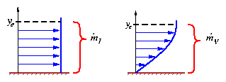
Figure shows the mass flux passing between the vertical extent y = 0 ¼ye for inviscid and viscous flows with the same edge velocity.

mass_compare.gif

Figure 1: Comparison of inviscid and viscous mass flows

.
m
 

I 
   =    ó
õ
d .
m
 
   =    ó
õ
ye

0 
ru  dy    =    .
m
 

I 
   =   re ue ye
.
m
 

V 
   =    ó
õ
d .
m
 
   =    ó
õ
ye

0 
ru  dy    =   re ue ye  -  ó
õ
ye

0 
(re ue - ru ) dy    =    .
m
 

I 
 - re ue d*
The viscous mass flow is decreased by an amount equal to the mass defect re ue d*.

2.2  Momentum flow comparison

Figure shows the momentum flux carried by the mass flow passing between y = 0 ¼ye of the inviscid case. The viscous case capture height is increased by d* so that the comparison is done at the same mass flows. In each case, the momentum flow can be considered to be the force acting on a barrier which arrests the flow velocity to zero.

mom_compare.gif

Figure 2: Comparison of inviscid and viscous momentum flows, at the same mass flow

FI    =    ó
õ
u d .
m
 
   =    ó
õ
ye

0 
ru2  dy    =   FI    =   re ue2 ye
FV    =    ó
õ
u d .
m
 
   =    ó
õ
ye+d*

0 
ru2  dy    =   re ue2 ye  -  ó
õ
ye+d*

0 
(ue - u ) ru dy    =   FI  - re ue2 q
The viscous momentum flow is decreased by an amount equal to the momentum defect re ue2 q.

2.3  Kinetic energy flow comparison

Figure shows the kinetic energy flux carried by the mass flow passing between y = 0 ¼ye of the inviscid case. The viscous case capture height is again increased by d* so that the comparison is done at the same mass flows. In each case, the kinetic energy flow can be considered to be the power generated on an array of perfect windmills which reversibly bring the flow velocity to zero.

mom ke_compare.gif

Figure 3: Comparison of inviscid and viscous kinetic energy flows, at the same mass flow

PI    =    ó
õ
1
2
u2 d .
m
 
   =    ó
õ
ye

0 
1
2
ru3  dy    =   PI    =    1
2
re ue3 ye
PV    =    ó
õ
1
2
u2 d .
m
 
   =    ó
õ
ye+d*

0 
1
2
ru3  dy    =    1
2
re ue3 ye  -  ó
õ
ye+d*

0 
1
2
(ue2 - u2 ) ru dy    =   PI  -  1
2
re ue3 q*
The viscous kinetic energy flow is decreased by an amount equal to the kinetic energy defect 1/2 re ue3 q*.