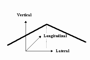
This tidbit should either totally confuse you or help clear up the simulation axis system. Since this is a computer representation of a 3 dimensional world, there are 2 axis systems that are in use, the "real" world axis system that is used to create the display scene, and the screen axis system that is used to draw it. These axis systems are completely different and although the screen axis system is not used much in the documentation, it is used occasionally. First the "real" world axis system and how it relates to where the driver is will be explained. The X axis is longitudinal out from the driver going down the road, and is positive forward. The Y axis system is lateral from left to right and is positive to the right. The Z axis system is vertical up and down and is positive up. When an event file parameter or configuration parameter requires "real" world data, these conventions are used. For the screen axis system, the X axis is left to right across the screen starting with 0 at the left hand side of the screen and ending with 1 at the right hand side of the screen. The Y axis is vertical up and down the screen starting with 0 at the bottom of the screen and ending with 1 at the top of the screen.

Another caveat dealing with distances and coordinates and such, deals with the lateral position of objects in the display scene. All "real" world objects are relative to the roadway’s dividing line. Not the center of the roadway, but the dividing line between traffic. This is simple if you have a divided roadway with traffic traveling in both directions and some type of a dividing line. But, what happens if you are using a road that only has traffic traveling in one direction, then what is the dividing line? This is a simple one, it is the left edge of the roadway, and everything will be relative to it.