Burt Rutan's White Knight and SpaceShip One, Photo Courtesy of Scaled Composites
Thermodynamics and Propulsion


11.3 Implications of propulsive efficiency for engine design

If we consider our expressions for thrust and propulsive efficiency together,

$\displaystyle F = \dot{m}(u_e - u_0) \qquad \textrm{and}\qquad \eta_{\textrm{prop}}=\cfrac{2}{1+\cfrac{u_e}{u_0}}$    

we see that

$\displaystyle \textrm{as}\quad\frac{u_e}{u_0}\uparrow \quad \frac{F}{\dot{m}u_0} \uparrow \quad \textrm{but} \quad \eta_{\textrm{prop}} \downarrow$    

$\displaystyle \textrm{and as}\quad \frac{u_e}{u_0}\rightarrow 1 \quad \frac{F}{\dot{m}u_0} \downarrow \quad \textrm{and} \quad \eta_{\textrm{prop}} \uparrow.$    

Also note that for

$\displaystyle \frac{F}{\dot{m}u_0} \uparrow \quad A_{\textrm{inlet}} \downarrow \quad \textrm{Drag} \downarrow,$    

where $ A_{\textrm{inlet}}$ is the inlet area of an engine, shown in Figure 11.1.

Figure 11.1: Schematic of the inlet area of an engine
Image fig3AInlet_web

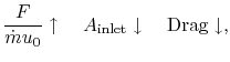
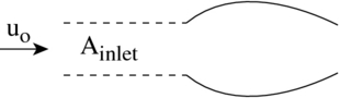
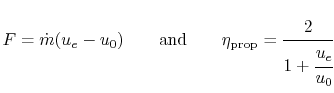
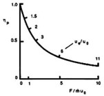
The balance between propulsive efficiency and specific thrust ($ \propto$ thrust per unit mass flow) is shown in Figure 11.2.

Figure 11.2: Propulsive efficiency and specific thrust as a function of exhaust velocity (Kerrebrock, 1991).
Image fig3EtaPropKerrebrock_web

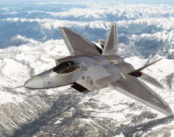
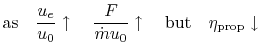
For fighter aircraft that need high thrust/weight and fly at high speed, it is typical to employ engines with smaller inlet areas and higher thrust per unit mass flow,

% latex2html id marker 49303
$\displaystyle \therefore \frac{u_e}{u_0} \uparrow \quad \textrm{and} \quad \eta_{\textrm{prop}} \downarrow.$    

The small inlet of one of the F-22 Raptor's two engines is visible just below the cockpit in Figure 11.3.

Figure 11.3: The F-22 Raptor (Copyright 1999 by Lockheed Martin).
Image fig3LockheedF22Raptor_web

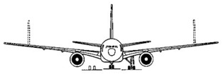
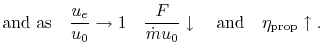
However, transport aircraft that require higher efficiency and fly at lower speeds usually employ engines with relatively larger inlet areas and lower thrust per unit mass flow,

% latex2html id marker 49308
$\displaystyle \therefore \frac{u_e}{u_0} \rightarrow 1 \quad \textrm{and} \quad \eta_{\textrm{prop}} \uparrow.$    

The large inlets of a Boeing 777-200's engines are shown in Figure 11.4.

Figure 11.4: The Boeing 777-200 (Jane's, 1998-9).
Image fig3Boeing777200_web

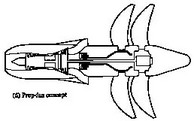
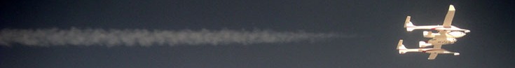
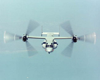
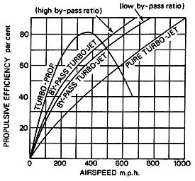
At low flight velocities, the highest propulsive efficiency is typically obtained with a propeller or an unducted fan. Figure 11.5 shows a propeller craft, and Figure 11.6 shows a sketch of a jet engine with an unducted fan. Figure 11.7 shows propulsive efficiency as a function of airspeed for different engine bypass ratios.

Figure 11.5: A propeller gives a relatively small impulse ($ \Delta u$ ) to a relatively large mass flow (Boeing, 2000)
Image fig3BoeingPropellers_web

Figure 11.6: An advanced, contour-rotating, unducted fan concept (Rolls-Royce, 1992)
Image fig3RollsUnducted_web

Figure 11.7: Propulsive efficiency comparison for various gas turbine engine configurations (Rolls-Royce, 1992)
Image fig3EtaPropRolls_web

UnifiedTP