Burt Rutan's White Knight and SpaceShip One, Photo Courtesy of Scaled Composites
Thermodynamics and Propulsion

11.8 Muddiest points on Chapter 11

MP 11..1   What exactly is the specific impulse, $ I_{sp}$ , a measure of?

The specific impulse is a measure of how well the fuel is used in creating thrust. For a rocket engine, the specific impulse is the effective exit velocity divided by the acceleration of gravity, $ g$ . In terms of relating the specific impulse to some characteristic time, we can write the definition of $ I_{sp}$ as

$\displaystyle I_{sp} \dot{m}g = F.$

From this, one can regard the specific impulse as the time that it would take to flow a quantity of fuel that has a weight equal to the thrust force.

MP 11..2   How is $ I_{sp}$ found for rockets in space where $ g \approx 0$ ?

The impulse $ I$ given to a rocket is the thrust force integrated over the burn time. Traditionally, for the case of constant exhaust velocity $ c_{ex}$ , the specific impulse has been used $ I_{sp} = I
/(m_p g) = c_{ex} / g_0$ , where $ m_p$ is the propellant mass and $ g_0$ is the Earth's surface gravity. Thus $ I_{sp}$ is measured in seconds and is a force per weight flow. Often today, however, specific impulse is measured in units meters/second [m/s], recognizing that force per mass flow is more logical. The specific impulse is then simply equal to the exhaust velocity $ I_{sp} =
c_{ex}$ .

MP 11..3   Why does industry use $ TSFC$ rather than $ I_{sp}$ ? Is there an advantage to this?

I am not sure why Thrust Specific Fuel Consumption was originally used. The gas turbine industry uses $ TSFC$ ; the rocket propulsion industry uses essentially its inverse, Specific Impulse. Perhaps an advantage is that $ TSFC$ is a number of magnitude unity, whereas specific impulse is not.

MP 11..4   Why isn't mechanical efficiency an issue with ramjets?

As defined, the mechanical efficiency represents bearing friction, and other parasitic torques on the rotating shaft in a gas turbine. The work associated with this needs to be provided by the turbine, but does not go into driving the compressor. The ramjet has no shaft, and hence does not encounter this.

MP 11..5   How is thrust created in a ramjet?

You can look at thrust in several ways. One is through the integral form of the momentum equation, which relates thrust to the difference between exit and inlet velocities, multiplied by the mass flow. Another way, however, is to look at the forces on the ramjet structure, basically the summation of pressure forces on all the surfaces. I attempted to do this in class using the turbojet with an afterburner. For the ramjet, from the same considerations, we would have an exit nozzle that was larger in diameter than the inlet so that the structural area on which there is a force in the retarding direction is smaller than the area on which there is a force in the thrust direction.

MP 11..6   What is the relation between $ h_{t4} - h_{t3} = f\Delta h_f$ and the existence of the maximum value of $ T_{t4}$ ?

The two are very different physical statements. The first is the SFEE (steady flow energy equation) plus the approximation that inlet and exit mass flows to the control volume are the same. The heat received within the volume is represented by the quantity $ f\Delta
h_f$ , where $ \Delta h_f$ is the heat liberated per kilogram of fuel. The second statement is a representation of the fact that the degree of completion of the reaction in the combustor depends on temperature, so that even though the inlet temperature increases strongly as the Mach number increases, the combustor exit temperature does not change greatly. This is an attempt to represent a complex physical process (or set of processes) in an approximate manner, not a law of nature.

MP 11..7   Why didn't we have a 2s point for the Brayton cycle with non-ideal components?

If we didn't, we should have, or I should at least have marked the point at which the compressor exit would be if the compression process was isentropic.

MP 11..8   What is the variable $ f_\textrm{stoich}$ ?

$ f_\textrm{stoich}$ is the fuel-to-air ratio for stoichiometric combustion, or in other words the fuel-to-oxygen ratio for a chemically correct combustion process during which all fuel is burnt and all oxygen is consumed doing it.

MP 11..9   Isn't it possible for the mixing of two gases to go from the final state to the initial state? If you have two gases in a box, they should eventually separate by density, right?

Let us assume that gas $ X$ is oxygen and gas $ Y$ is nitrogen. When the membrane breaks the entire volume will be filled with a mixture of oxygen and nitrogen. This may be considered as a special case of an unrestrained expansion, for each gas undergoes an unrestrained expansion as it fills the entire volume. It is impossible for these two uniformly mixed gases to separate without help from the surroundings or environment. A certain amount of work is necessary to separate the gases and to bring them back into the left and right chambers.

MP 11..10   How can $ T_4/T_0$ be the maximum turbine inlet temperature?

I agree that the $ T_4/T_0$ is a temperature ratio. If we assume constant ambient temperature then this ratio reflects the maximum cycle temperature. The main point was to emphasize that the higher your turbine inlet temperature the higher your power and efficiency levels.

MP 11..11   When there are losses in the turbine that shift the expansion in $ T$ -$ s$ diagram to the right, does this mean there is more work than ideal since the area is greater?

We have to be careful when looking at the area enclosed by a cycle or underneath a path in the $ T$ -$ s$ diagram. Only for a reversible cycle, the area enclosed is the work done by the cycle (see notes Section 6.3). Looking at the Brayton cycle with losses in compressor and turbine the net work is the difference between the heat absorbed and the heat rejected (from the 1st law). The heat absorbed can be found by integrating $ TdS = dQ$ along the heat addition process. The heat rejected during the cycle with losses in compressor and turbine is larger than in the ideal cycle (look at the area underneath the path where heat is rejected, this area is larger than when there are no losses (when $ ds_\textrm{due to irreversibilities} = 0$ ). See also muddy point 6.1. So we get less net work if irreversibilities are present. It is sometimes easier to look at work and heat (especially shaft work for turbines and compressors) in the $ h$ -$ s$ diagram because the enthalpy difference between two states directly reflects the shaft work (remember, enthalpy includes the flow work!) and / or heat transfer.

MP 11..12   For an afterburning engine, why must the nozzle throat area increase if the temperature of the fluid is increased?

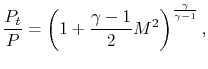
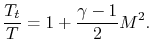
The Mach number of the flow is unity at the throat with and without the afterburner lit. The ratio of static pressure to stagnation pressure at the throat is thus the same with and without the afterburner lit. The ratio of static temperature to stagnation temperature at the throat is thus the same with and without the afterburner lit.

$\displaystyle \frac{P_t}{P} = \left(1+\frac{\gamma-1}{2}M^2\right)^{\frac{\gamma}{\gamma-1}},$

$\displaystyle \frac{T_t}{T} = 1+\frac{\gamma-1}{2}M^2.$

The flow through the throat is

$\displaystyle \dot{m} = \rho c A_\textrm{throat} = \rho a A_\textrm{throat} = \frac{P}{R T}\sqrt{\gamma R T}A_\textrm{throat}.$

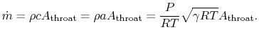
The flow through the throat thus scales as

$\displaystyle \frac{\dot{m}_\textrm{A/B}}{\dot{m}_\textrm{no A/B}} =
\cfrac{\le...
...textrm{A/B}}{\left(\cfrac{P}{\sqrt{T}}A_\textrm{throat}\right)_\textrm{no A/B}}$

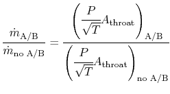
From what we have said, however, the pressure at the throat is the same in both cases. Also, we wish to have the mass flow the same in both cases in order to have the engine operate at near design conditions. Putting these all together, plus use of the idea that the ratio of stagnation to static temperature at the throat is the same for both cases gives the relation

$\displaystyle \frac{A_\textrm{throat A/B}}{A_\textrm{throat no A/B}} = \sqrt{\frac{T_\textrm{t, A/B}}{T_\textrm{t, no A/B}}}.$

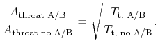
The necessary area to pass the flow is proportional to the square root of the stagnation temperature. If too much fuel is put into the afterburner, the increase in area cannot be met and the flow will decrease. This can stall the engine, a serious consequence for a single engine fighter.

MP 11..13   Why doesn't the pressure in the afterburner go up if heat is added?

From discussions after lecture, the main point here seems to be that the process of heat addition in the afterburner, or the combustor, is not the same as heat addition to a gas in a box. In that case the density (mass/volume) would be constant and, from $ P =\rho RT$ , increasing the temperature would increase the pressure. In a combustor, the geometry is such that the pressure is approximately constant; this happens because the fluid has the freedom to expand so the density decreases. From the equation $ P =\rho RT$ if the temperature goes up, the density must go down.

MP 11..14   Why is the flow in the nozzle choked?

As seen in Unified, choking occurs when the stagnation to static pressure ratio $ (P_t/P)$ gets to a certain value, $ 1.89$ for gas with $ \gamma$ of 1.4. Almost all jet aircraft aircraft operate at flight conditions such that this is achieved. If you are not comfortable with the way in which the concepts of choking are laid out in the Unified notes, please see me and I can give some references.

MP 11..15   What's the point of having a throat if it creates a retarding force?

As shown in Unified, to accelerate the flow from subsonic to supersonic, i.e., to create the high velocities associated with high thrust, one must have a converging-diverging nozzle, and hence a throat.

MP 11..16   Why isn't the stagnation temperature conserved in this steady flow?

Heat is added in the afterburner, so the stagnation temperature increases.

UnifiedTP