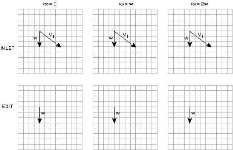
a) Draw velocity triangles in the relative and absolute frames for the different blade speeds shown below for both the inlet and exit to the rotor. (Note the inlet velocity components form a 3-4-5 triangle.)

b) For the three cases drawn in part a), which extracts the most power from the flow and why?
c) If you were asked to design for maximum power extraction and could choose any blade speed between 0 and rw = 2w, what speed would you choose?
You can argue this either graphically or with reference to the Euler Turbine Equation:
![]()
d) For what rotational speed does the "turbine" in this example, begin to act like a compressor? What might you expect the aerodynamic performance to be for the blades in such a situation - good or bad, and why?