UNIFIED ENGINEERING Spring 2006
Ian A. Waitz
Problem P8. (Propulsion) L.O. G
Below is a schematic of the first two blade rows in a turbine: the nozzle and the first stage rotor. The nozzle accelerates the combustor exit flow (low kinetic energy, high internal energy), giving it high axial and tangential velocity (converting the internal energy to kinetic energy).
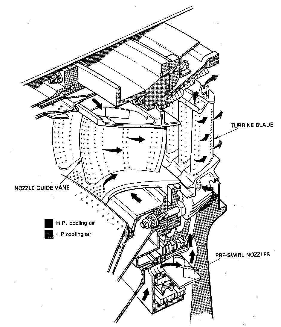
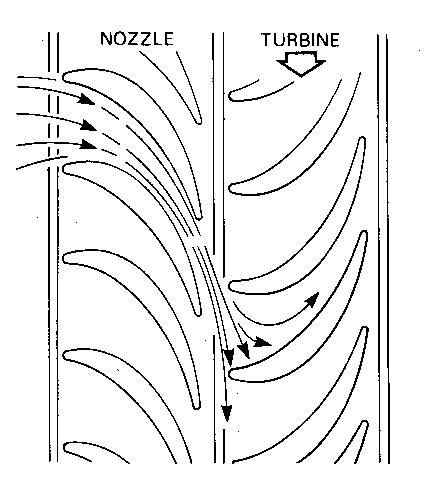
(Graphics from Rolls-Royce, “The Jet Engine”)
a) Neatly draw and label the velocity triangles assuming the blade speed wr = 540 m/s, where w =200 m/s is the axial velocity (and is assumed to be constant at inlet and exit of each blade row). Assume the exit flow angle of the stator is 70 degrees and the exit flow angle of the rotor is -70 degrees.
b) On which blade row(s) is there a torque applied? Why? In what direction does it act?
c) Calculate the power extracted by each blade row for a mass flow of 20 kg/s.
d) Draw the velocity triangles for a blade speed of wr = 500 m/s. Assuming the flow is well behaved, does the power per unit mass flow increase or decrease and by how much (percent change)? What aerodynamic problems might be encountered at this condition?
[NOTE: There is a Java applet in the online notes that will help you draw the velocity triangles – saves you from doing the trig.]
![]()