
III. Efficiencies of A/C Engines
In the first lecture we arrived at general expressions that related the thrust of a propulsion system to the net changes in momentum, pressure forces, etc. Now we will look at how efficiently the propulsion system converts one form of energy to another on its way to producing thrust.
A. Overall Efficiency
Thus
![]()
B. Thermal and Propulsive Efficiency
It is often convenient to break the overall efficiency into two parts: thermal efficiency and propulsive efficiency where
such that
hoverall = hthermal × hprop
The thermal efficiency in this expression is the same as that which we used extensively in Thermodynamics during Fall term. For an ideal Brayton cycle it is a function of the temperature ratio across the compressor.
![]()
Note that we can use our expression for thrust to rewrite the equation for propulsive efficiency in a more convenient form
![]()
Then
C. Implications of propulsive efficiency for engine design
If we consider our expressions for thrust and propulsive efficiency together
![]() and
and

we see that
as ![]() but
but ![]()
and as ![]() and
and ![]()
|
Also note that for |
|
|
The balance between propulsive efficiency and specific thrust (~ thrust per unit mass flow) is shown in Figure 3.1.
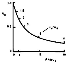
Figure 3.1 Propulsive efficiency and specific thrust as a function of exhaust velocity (Kerrebrock, 1991).
For fighter aircraft that need high thrust/weight and fly at high speed, it is typical to employ engines with smaller inlet areas and higher thrust per unit mass flow
![]() and
and ![]()
Figure 3.2 The F-22 Raptor (Copyright 1999 by Lockheed Martin).
However, transport aircraft that require higher efficiency and fly at lower speeds usually employ engines with relatively larger inlet areas and lower thrust per unit mass flow
![]() and
and ![]()
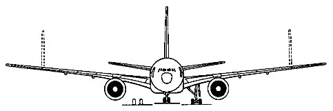
Figure 3.3 The Boeing 777-200 (Janes, 1998-9).
At low flight velocities, the highest propulsive efficiency is typically obtained with a propeller or an unducted fan.
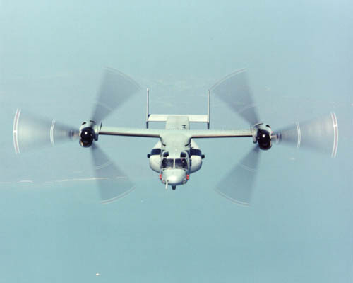
Figure 3.4 A propeller gives a relatively small impulse (Du) to a relatively large mass flow. (Boeing, 2000)
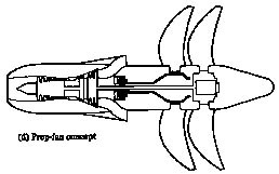
Figure 3.5 An advanced, contour-rotating, unducted fan concept (Rolls-Royce, 1992).
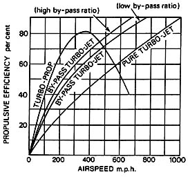
Figure 3.6 Propulsive efficiency comparison for various gas turbine engine configurations (Rolls-Royce, 1992).
![]()
D. Other expressions for efficiency
Sometimes the overall efficiency of aircraft engines is expressed in alternative parameters: specific impulse, I, and thrust specific fuel consumption, TSFC or just SFC. Both of these parameters have dimensions.
Specific Impulse (I or Isp):
![]() (units of seconds)
(units of seconds)
Specific Fuel Consumption (SFC or TSFC):
![]() (lbm/hr/lbf or kg/s/N)
(lbm/hr/lbf or kg/s/N)
E. Trends in thermal and propulsive efficiency
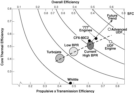
Figure 3.7 Trends in aircraft engine efficiency (after Pratt & Whitney).
Trends in thermal efficiency are driven by increasing compression ratios and corresponding increases in turbine inlet temperature as shown in Figures 3.8 and 3.9. Whereas trends in propulsive efficiency are due to generally higher bypass ratio engines.
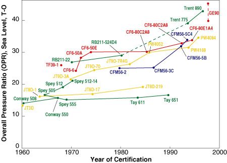
Figure 3.8 Pressure ratio trends for commercial transport engines (Epstein, 1998).
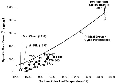
Figure 3.9 Trends in turbine inlet temperature (Koff, 1991).
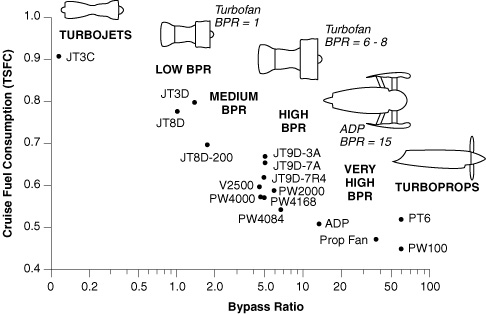
Figure 3.10 Trends in engine bypass ratio (Epstein, 1998).
| << Previous | Unified Propulsion | Next >> |