|
|
|
| Thermodynamics and Propulsion | |
3.8 Muddiest points on Chapter 3
MP 3..1
How can we idealize fuel addition as heat addition?
The validity of an approximation rests on what the answer is going to be used for. We are seeking basically only one item concerning combustor exit conditions, namely the exit temperature or the exit enthalpy. The final state is independent of how we add the heat, and depends only on whether we add the heat. If it is done from an electrical heater or from combustion, and if we neglect the change in the constitution of the gas due to the combustion products (most of the gas is nitrogen) the enthalpy rise is the same no matter how the temperature rise is achieved.
MP 3..2
Since
This is correct. However, there is a limit on the maximum achievable efficiency. We cannot convert the absorbed heat into 100% work, that is, we always must reject some amount of heat. The amount of heat we must reject is
Thus for given values of
MP 3..3
In the Carnot cycle, why are we only dealing with volume
changes and not pressure changes on the adiabats and isotherms?
We are not neglecting the pressure terms and we are also dealing
with pressure changes. On the adiabats we know that
By arranging terms we obtain
For a process we can integrate from 1 to 2 and get
During an isothermal process, the temperature stays constant. Using
the equation of state for an ideal gas,
MP 3..4
Is there a physical application for the Carnot cycle? Can we
design a Carnot engine for a propulsion device?
We will see that Carnot cycles are the best we can do in terms of efficiency. A constant temperature heat transfer process is, however, difficult to attain in practice for devices in which high rates of power are required. The main role of the Carnot engine is therefore as a standard against which all other cycles are compared and which shows us the direction in which design of efficient cycles should go.
MP 3..5
How do we know which cycles to use as models for real
processes?
We have discussed this briefly for the Brayton cycle, in that we looked at the approximation that was made in saying heat addition occurred at constant pressure. You can also see that the Carnot cycle is not a good descriptor of a gas turbine engine! We will look further at this general point, not only for the Brayton cycle, but also for the Rankine cycle and for some internal combustion engine cycles. I will try to make clear what are the approximations and why the cycle under study is being used as a model.
MP 3..6
How is
For now, we rely on tabulated values. In the lectures accompanying
Chapter 15 of the notes, we will see how one can
calculate the heat,
MP 3..7
What are ``stoichiometric conditions?''
Stoichiometric conditions are those in which the proportions of fuel and air are such that there is not an excess of either one in the combustion reaction -- all the fuel is burned, and all the air (oxidizer) is used up in the reaction. See Chapter 15.
MP 3..8
When and where do we use
The answer is no. The definitions of
For a process during which heat
where both the heat transferred
Similarly we can do an experiment involving a process where the
pressure is kept constant during the reversible heat transfer
MP 3..9
Explanation of the above comparison between Diesel and
Otto.
Basically we can operate the diesel cycle at much higher compression ratio than the Otto cycle because only air is compressed and we don't run into the auto-ignition problem (knocking problem). Because of the higher compression ratios in the diesel engine we get higher efficiencies.
MP 3..10
Would it be practical to run a Brayton cycle in reverse and
use it as refrigerator?
Yes. In fact people in Cryogenics use reversed Brayton cycles to cool down systems where very low temperatures are required (e.g., space applications, liquefaction of propellants). One major difference between a regular Brayton cycle (such as a jet-engine or a gas-turbine) and a reversed Brayton cycle is the working fluid. In order to make a reversed Brayton cycle practical we have to choose a working fluid that is appropriate for the application. Extremely low temperatures can be achieved when using a regenerator -- a heat exchanger that preheats the fluid before it enters the compressor and cools the fluid further down before it enters the turbine. In this configuration the fluid is expanded to much lower temperatures, and more heat can be absorbed from the cooling compartment.
MP 3..11
When flow is accelerated in a nozzle, doesn't that reduce
the internal energy of the flow and therefore the enthalpy?
Indeed both enthalpy and internal energy are reduced. The stagnation enthalpy is the quantity that is constant.
MP 3..12
Why do we say that the combustion in a gas turbine engine is
at constant pressure?
This is an approximation, and a key question is indeed how accurate
it is and what the justification is. The pressure change in the
combustor can be analyzed using the one-dimensional compressible
flow equations. The momentum equation is
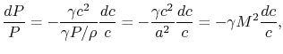
where
Changes in velocity are due to changes in density and in
flow-through area
Hence
Differentiating,
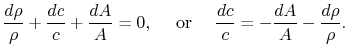
Velocity changes are therefore related to area changes (geometry)
and density changes (basically heat input). For a gas turbine
combustion process the change in density is comparable with (a
significant fraction of) the initial density and the area change is
several times the initial area. This means that the change in
velocity divided by the initial velocity is roughly of the
order of magnitude of unity. The momentum equation thus tells us
that for small Mach number (say 0.1) the ratio The rapidity of the combustion process does not really have anything to do with this approximation. We could have a process, such as a nozzle, in which there was combustion at the same time that the pressure was dropping. As seen from the momentum equation, the heat addition does not ``directly'' affect the pressure -- changes in pressure are associated with changes in velocity.
MP 3..13
Why is the Brayton cycle less efficient than the Carnot
cycle?
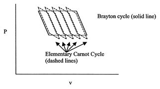
Consider the Brayton cycle and the corresponding work done as being approximated by a number of elementary Carnot cycles, as shown by the dashed lines in Figure 3.26. All of these Carnot cycles have the same pressure ratio, thus the same temperature ratio, and thus the same efficiency. The temperature ratio that figures into the efficiency of the elementary Carnot cycles is the inlet temperature divided by the compressor exit temperature, not the maximum cycle temperature, which is at the combustor exit. The basic reason for the lower efficiency is that heat is absorbed at an average temperature that is lower than the maximum temperature and rejected at an average temperature higher than the minimum temperature. We will come back to this important point (which has implications for all cycles), but if you cannot wait, see Chapter 6 of the notes.
MP 3..14
If the gas undergoes constant pressure cooling in the
exhaust outside the engine, is that still within the system
boundary?
When we analyze the state changes as we trace them around the cycle, we are viewing the changes in a system, a mass of fixed identity. Thus we follow the mass as it moves through the device and the cooling of the gas outside the engine is happening to our system.
MP 3..15
Does it matter what labels we put on the corners of the
cycle or not?
It does not matter what labels we use on the corners of the cycle. A cycle is a series of processes. Independent of where you start in the cycle, it always brings you back to the state where you started.
MP 3..16
Is the work done in the compressor always equal to the work
done in the turbine plus work out (for a Brayton cyle)?
NO. The work done in the compressor plus net work out equals the total turbine work. Using the 1st law, the net work we get out of the Brayton cycle is
(see notes for details). Rearranging the temperatures we can also write
Thus the net work is the difference between the enthalpy drop across the turbine (we get work from the turbine) and the enthalpy rise through the compressor (we have to supply work to the compressor).
MP 3..17
What are the units of
The units of power are J/s (kJ/s, MJ/s) or Watts (kW, MW). The mass
flow is kg/s. The units of
MP 3..18
Question about the assumptions made in the Brayton cycle for
maximum efficiency and maximum work.
We have first derived a general expression for the thermal efficiency of an ideal Brayton cycle (see Equation 3.10). The assumptions we made for the cycle were that both the compressor and turbine are ideal, such that they can be modeled adiabatic and reversible. We then looked at possible ideal Brayton cycles that would yield (A) maximum efficiency and (B) maximum work, keeping the assumptions of an ideal cycle (the assumptions of adiabatic and reversible compression and expansion stem from the choice of an ideal cycle).
One way to construct an ideal Brayton cycle in the
For the derivation of
MP 3..19
You said that for a gas turbine engine modeled as a Brayton
cycle the work done is
Using the 1st law, the net work we get out of the cycle is
(see notes for details). Rearranging the temperatures we can also write
Thus the net work is the difference between the enthalpy drop across the turbine (we get work from the turbine) and the enthalpy rise through the compressor (we have to supply work to the compressor, this is done through the drive shaft that connects turbine and compressor).
In class we analyzed an ideal Brayton cycle with the
assumptions of adiabatic reversible compression and expansion
processes, meaning that the work done by the turbine is the
maximum work we can get from the given turbine (operating
between
MP 3..20
Why don't we like the numbers 1 and 2 for the stations? Why
do we go 0-3?
A common convention in the industry is that station 0 is far upstream, station 1 is after the shock in the inlet (if there is one), station 2 is at inlet to the compressor (after the inlet/diffuser) and station 3 is after the compressor. In class, when we examined the ramjet we considered no changes in stagnation pressure between 0 and 2, so I have used 0 as the initial state for the compression process. It would be more precise to differentiate between stations 0 and 2, and I will do this where appropriate.
MP 3..21
For the Brayton cycle efficiency, why does
Douglas Quattrochi
2006-08-06
The ramjet is operating as a Brayton cycle where
|