


2.00b Toy Product Design
Let's Play - Toobers!
Final Assembly 4 The Electronic Insides
A Quick Refresher
Whoohoo! Time to add the insides! At this point, you should be able to put your two halves (top and bottom) together. Note the alignment of the screw hole. You can also see the lock/unlock symbol on the bottom of your Toobers.
Before starting, test the PCB and electronics to make sure it plays as you expect, and that it didn't shift or get disconnected during transit. If anything seems off, try to determine the cause, and work to resolve it before proceeding.
Some Disassembly Required
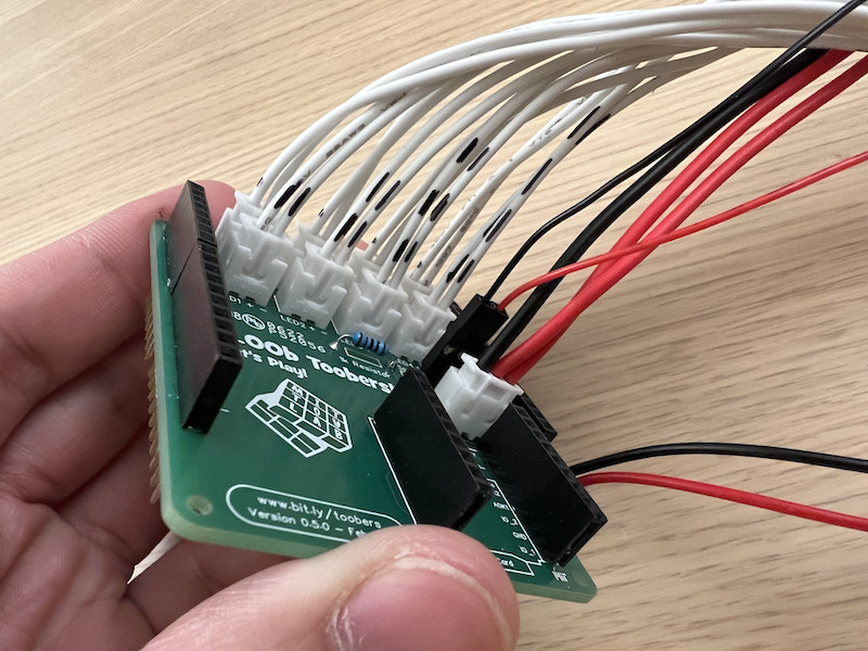
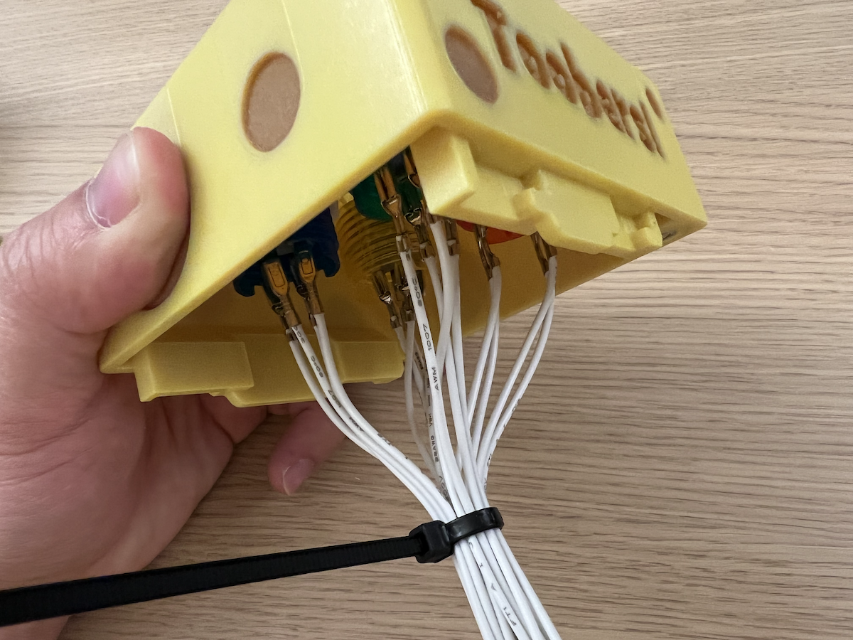
We're going to unplug the buttons and toggle switch so we can feed the wires for those into the holes through your Toobers. Before removing anything, grab a sharpie and label the wires in a way that'll help you remember which plug goes into which connector on the PCB. This will save you time later.
Below is an example of how you could label your wires. A series of dashes for the LED side, from 1 to 4 dashes. You'll want to do the same for the buttons (the row of connectors not shown in the photo below) but in a different color. Remember - don't mix these up, or you might short your circuit!
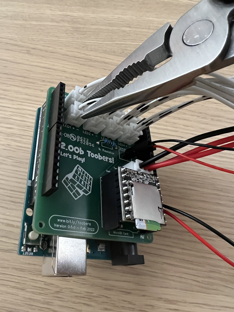
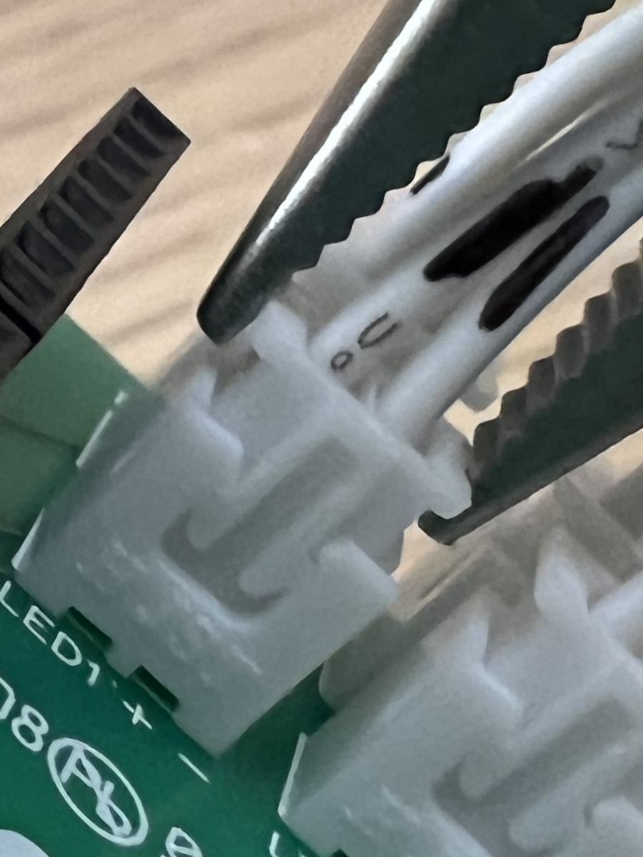
To remove the connectors, avoid pulling on the wires directly. We have needle nose pliers that you can use to pinch on the plastic part to separate the two pieces so that we reduce the chances of an undesirable wire rip-out.
Buttons
Let's start by attaching the buttons to the top housing of your toobers. Unscrew the threaded ring for each button, place the buttons in the holes, and screw the ring back on by threading it in from underneath. If you have a tight geometry, needle nose pliers may also help you here to tighten the plastic ring. Do this for all 4 buttons.
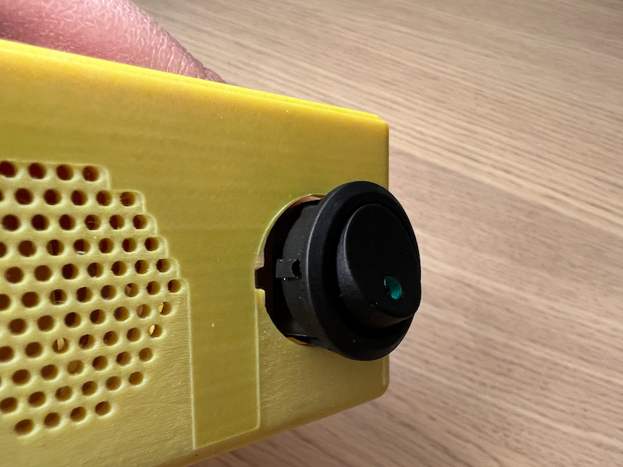
Toggle Power Switch
The toggle switch snaps into the hole. Note the indentation in the enclosure, and then note the protruding alignment pin on the toggle switch. This helps you align the switch and prevents it from rotating. Gently push the switch in while providing support on the sides of your Toobers wall to prevent the walls from cracking.
Sticky Foam Tape!
Grab 3 pieces of double stick foam tape and place it on the various locations where you'll be placing the components in the bottom housing - the battery, the speaker, and the Arduino/PCB.
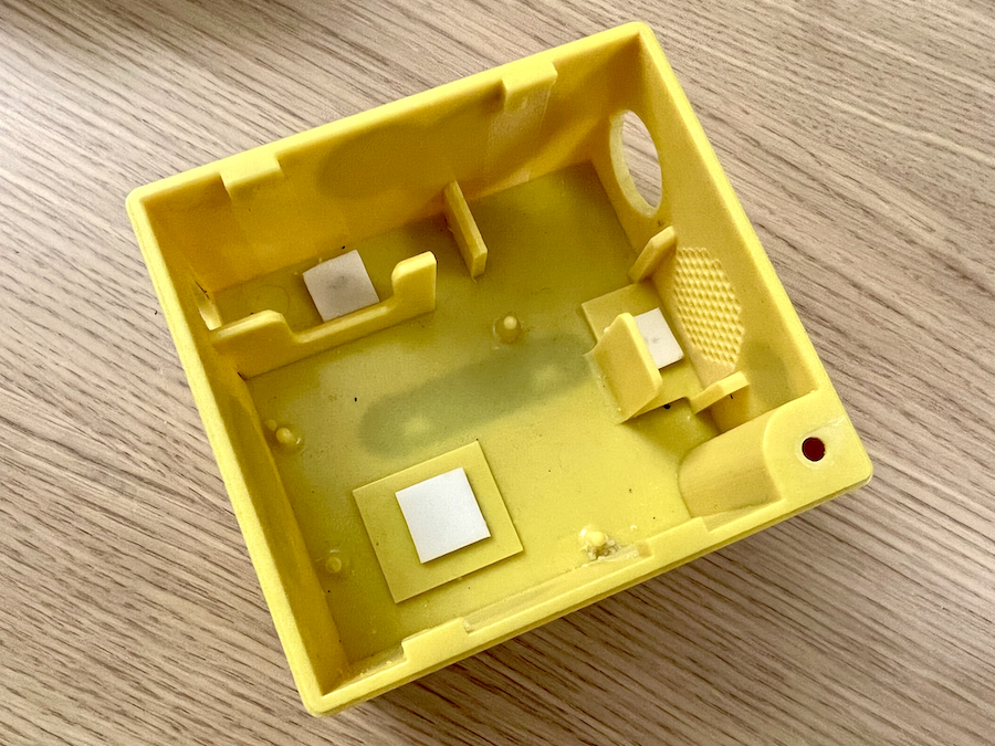
Place the...
- Arduino in the housing noting the aligning pins on the bottom enclosure, and the holes in the Arduino.
- The speaker in the housing such that the wire comes out to the side, and press it down into the foam tape.
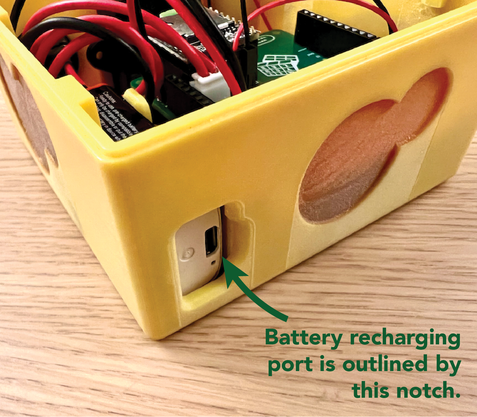
- The battery in the housing noting the orientation of the recharging port and how the wire comes out. (see the image below - your recharging port should look like that in the end.)
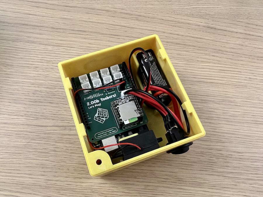
The final result should look something like this!
Connect the Halves!
Finally, lay the two halves of your toobers side by side, and attach the cables you previously removed for the buttons and the toggle switch back into the PCB. Once you've done that, everything should be connected. Turn it on to test it to see if it still works!
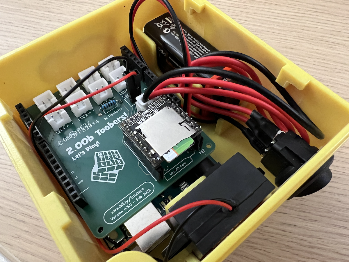
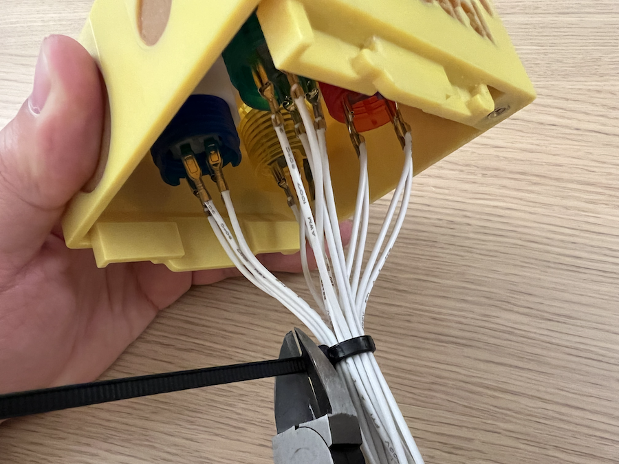
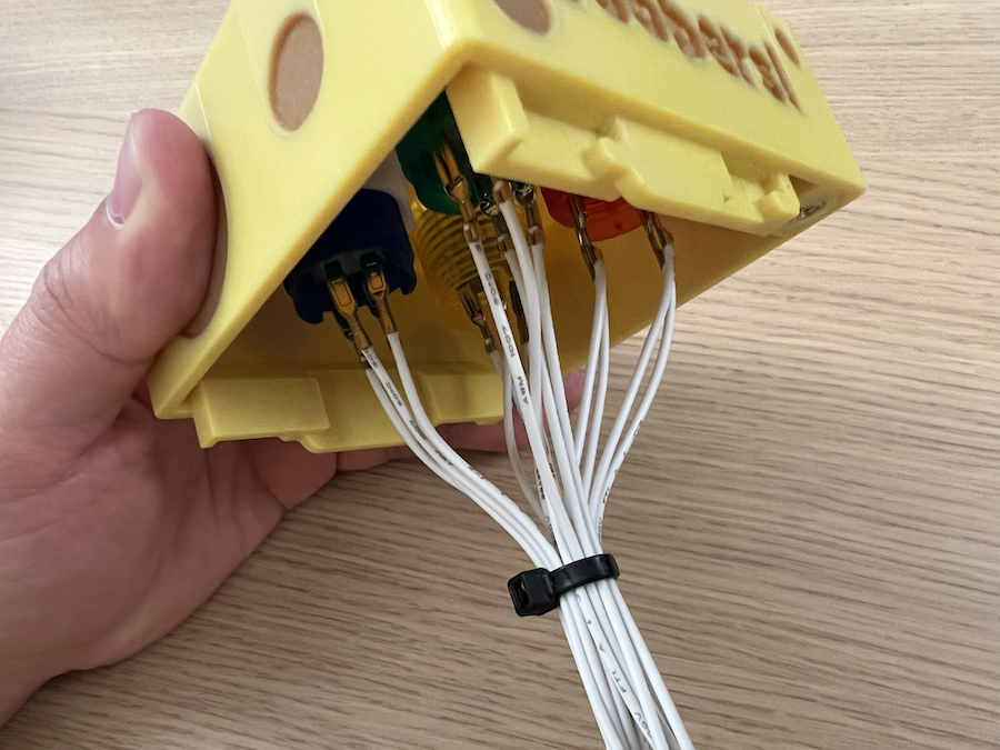
Zipties
With a lot of wires, things can get messy! Use a zip tie to create a flexible 'wiring harness' for all your wires, so that you can manage them easier. Use a flush cutter to trim off any excess. One or two zipties should do the trick.
Close it up!
Close up your friend, careful not to pinch any wires as you put the two halves together.
Test your Toobers again! It's good to get into the process of regularily testing, so you know to immediately stop and backtrack if something doesn't work. If anything comes loose in the assembly process or in transit, you can always re-solder.
Once everything looks good, use the 6mm-long M3 Flat Head Phillips Screw to hold everything together, and… you're done!
Documentation
Before you leave, be sure to get a product photo of your Toobers with Danny. This photo will go into your portfolio! Congratulations! You're finished your Toobers toy!