The Step-sensing Floor
The key point of the design is to transform the load signal when people step on the floor into electrical signals to oprate light and laser switches. The design refers the electrical weight scale. When four load cells on each corner receive loads, they output voltage signals to the scale’s PCB boards and ignites the display device. In our case, the PCB board is linked to the Arduino instead, which controls all the switches for the laser and light.

Here is a look-like model of the entire system. Electrical components are on the way due to the long lead time.

A thin layer of the circuit assembly are put between the floor and the ground. As like the electrical weight scale, the load cell undergoes fine displacements so that players hardly recognize descent of the floor.
A simulated internal structure of the circuit assembly is shown below. As the load cell receives load from the player, related voltage signals are sent to the PCB board, amplified and then sent to the Arduino so that the Arduino could operate switches.

A flowchart is shown below how it works:
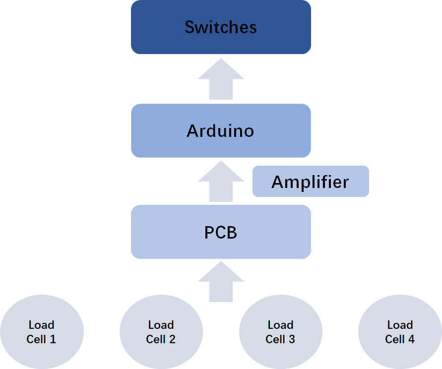
When at least one of the four load cells on each side of the floor (four cells on each corner to make sure detection correct) receive loads from the players, cells output voltage signals to the PCB board. Since the voltage signal is tool small ( 5mV level), an amplifier (AD620) is used to amplify the signal into the Arduino’s receivable level (5V). After receiving signals, Arduino controls the switches of lights and laser light.