 |
|
| COMPRESSION REFRIGERATION SYSTEM | ||
| QUESTIONS OR COMMENTS | ||
 |
AUTHOR: | Roger Yeh |
| E-MAIL: | ryeh@MIT.EDU | |
| COURSE: | 2 | |
| CLASS/YEAR: | 1 | |
MAIN FUNCTIONAL REQUIREMENT: Remove heat from an enclosed region.
DESIGN PARAMETER: Compression refrigeration systems.
GEOMETRY/STRUCTURE:
Refrigerant, compressor, expansion valve (flow control device), evaporator, condenser, pipes and tubes.
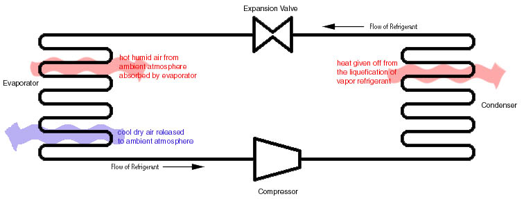 |
| Skematic of Compression Refrigeration System |
EXPLANATION OF HOW IT WORKS/ IS USED:
Refrigerant flows through the compressor, which raises the pressure of the refrigerant. Next the refrigerant flows through the condenser, where it condenses from vapor form to liquid form, giving off heat in the process. The heat given off is what makes the condenser "hot to the touch." After the condenser, the refrigerant goes through the expansion valve, where it experiences a pressure drop. Finally, the refrigerant goes to the evaporator. The refrigerant draws heat from the evaporator which causes the regrigerant to vaporize. The evaporator draws heat from the region that is to be cooled. The vaporized refrigerant goes back to the compressor to restart the cycle.
More Detail:
Compressor: Of the reciprocating, rotary, and centrifugal compressors, the most popular among domestic or smaller power commercial refrigeration is the reciprocating. The reciprocating compressor is similar to an automobile engine. A piston is driven by a motor to "suck in" and compress the refrigerant in a cylinder. As the piston moves down into the cylinder (increasing the volume of the cylinder), it "sucks" the refrigerant from the evaporator. The intake valve closes when the refrigerant pressure inside the cylinder reaches that of the pressure in the evaporator. When the piston hits the point of maximum downard displacement, it compresses the refrigerant on the upstroke. The refrigerant is pushed through the exhaust valve into the condenser. Both the intake and exhaust valves are designed so that the flow of the refrigerant only travels in one direction through the system.
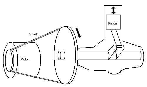 |
| Diagram of Compressor (Belt Driven In This Instance) |
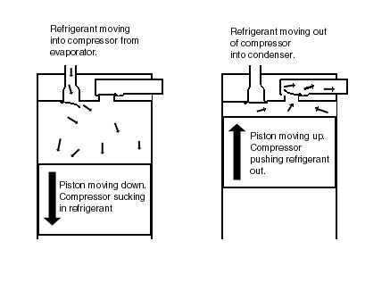 |
| Detail of Compressor Valve Function |
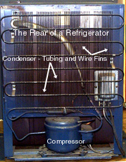 Components of Compresion Refrigeration In A Dorm Refrigerator |
Condenser: The condenser removes heat given off during the liquefication of vaporized refrigerant. Heat is given off as the temperature drops to condensation temperature. Then, more heat (specifically the latent heat of condensation) is released as the refrigerant liquefies. There are air-cooled and water-cooled condensers, named for their condensing medium. The more popular is the air-cooled condenser. The condensers consist of tubes with external fins. The refrigerant is forced through the condenser. In order to remove as much heat as possible, the tubes are arranged to maximize surface area. Fans are often used to increase air flow by forcing air over the surfaces, thus increasing the condenser capability to give off heat. |
Evaporator: This is the part of the refrigeration system that is doing the actual cooling. Because its function is to absorb heat into the refrigeration system (from where you don't want it), the evaporator is placed in the area to be cooled. The refrigerant is let into and measured by a flow control device, and eventually released to the compressor. The evaporator consists of finned tubes, which absorbs heat from the air blown through a coil by a fan. Fins and tubes are made of metals with high thermal conductivity to maximize heat transfer. The refrigerant vaporizes from the heat it absorbs heat in the evaporator.
Flow control device (expansion valve): This controls the flow of the liquid refrigerant into the evaporator. Control devices usually are thermostatic, meaning that they are responsive to the temperature of the refrigerant.
DOMINANT PHYSICS:
 |
All variables are in units of per unit mass.
| Variable | Description | Metric Units | English Units |
| h1, h2, h3, h4, hi | Enthalpies at stages i | kJ/kg | Btu/lbm |
| qin | Heat into the system | kJ/kg | Btu/lbm |
| qout | Heat out of system | kJ/kg | Btu/lbm |
| work | work into the system | kJ/kg | Btu/lbm |
| b | coefficient of performance | -- | -- |
Thermodynamics
From stage 1 to stage 2, the enthalpy of the refrigerant stays approximately constant, thus
h1 ~ h2.
From stage 2 to stage 3, heat is put into the system, thus
qin = h3 – h2 = h3 – h1.
From stage 3 to stage 4, work is put into compressor, thus
work = h4 – h3.
From stage 4 to stage 1, heat is given off through the condenser, thus
qout = h4 – h1.
The coefficient of performance describes the efficiency the evaporator to absorb heat in relation to the work put in, thus
b = refrigeration effect / work input = qin / work = (h3 – h1) / (h4 – h3).
LIMITING PHYSICS:
Heat transfer depends on the properties of the refrigerant. Different refrigerants will obviously have different enthalpy values for a given state. In dealing with one specific refrigerant, the enthalpy values depend on the temperatures and pressures in the warm and cold regions. The surrounding temperature affects how well the refrigeration system is able to cool the enclosed region. Clearly, if the outside temperature is very hot (i.e. much above room temperature), the system may not be as successful in lowering the temperature of the enclosed region as it would at room temperature.
PLOTS/GRAPHS/TABLES:
None Submitted
WHERE TO FIND COMPRESSION REFRIGERATION SYSTEMS:
Refrigerators and air conditioners.
REFERENCES/MORE INFORMATION:
Moran, Michael J. and Shapiro, Hoaward N., Fundamentals of Engineering Thermodynamics, New York: John Wiley & Sons, Inc., ė 1992.
Langley, Billy C., Refrigeration and Air Conditioning, Reston Virginia: Reston Publishing Company, Inc., ė 1982.