 |
|
| CORDLESS DRILL | ||
| QUESTIONS OR COMMENTS | ||
 |
AUTHOR: | Todd (Henry) Atkins |
| E-MAIL: | todd@MIT.EDU | |
| COURSE: | 6 - 2 | |
| CLASS/YEAR: | 2 | |
MAIN FUNCTIONAL REQUIREMENT: Provide portable method for drilling holes and driving fasteners
DESIGN PARAMETER: Cordless drill
GEOMETRY/STRUCTURE:
|
| Diassembled Cordless Drill |

EXPLANATION OF HOW IT WORKS/ IS USED:
| Planetary Gearbox The gearbox consists of a series of planetary gears. The sun gear turns to move the planet gears that roll along the inside edge of the fixed ring gear. The planet carrier has a gear on its opposite face that acts as the sun gear for the next planetary gear set. In this manner, the reductions of each successive planetary set can be coupled together. |
 |
| Clutch The clutch allows the driver head to disengage from the gearbox when the motor applies more than a specified torque. The breaking torque of the clutch is adjusted by the tension on the springs in the clutch assembly. The collar screws in or out to tighten or loosen the springs respectively. This is used to adjust the slip of the clutch. |
 |
| Trigger and PWM Controller The trigger mechanism controls the speed of the motor while maintaining high efficiency. Pulse width modulation or PWM uses a wave of fixed frequency to transmit power to the motor. The controller drives the voltage between 100% on and 100% off for a certain fraction of each wavelength. This fraction is referred to as the duty cycle. In this drill the voltage is driven between zero and eighteen volts and is controlled by the transistor. In effect, the motor turns on and off very rapidly. |
 |
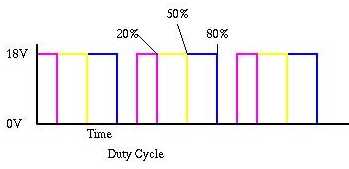 |
| Duty Cycle |
This signal appears "time averaged" as the shaft speed. In a low duty cycle the motor is getting a very short pulse. It is turning on, then off quickly and there is a relatively long time before it turns on again. This on/off switching appears as a constant slow speed. At higher duty cycles the voltage of the pulse is still constant but the length of the pulse per unit time is greater. Since the motor is on for a longer percentage of time it spins faster. The duty cycle is a measure of the relative width of the pulse in time and determines the speed of the output shaft.
There are two main advantages to a PWM controller. The first is the size and relative ease with which it can be implemented. The circuit consists of a timer and a transistor. The trigger controls the timer. The second advantage is its efficiency. The transistor acts as a switch and is therefore either on or off. Theoretically this will dissipate no power. Minimizing the loss in the control circuitry means longer runtime for the drill and that a greater percentage of the power is transferred to the motor.
DC Motor
This drill uses a DC (direct current) motor with replaceable brushes. It is capable of a nearly constant torque output.
DOMINANT PHYSICS:
| Variable | Description | Metric Units | English Units |
| Pin | Input power from battery | Horsepower | Watts |
| Pout | Output power at chuck | Horsepower | Watts |
| Ploss | Dissipated power | Horsepower | Watts |
| w | Rotational speed of shaft | RPM | Radians/Sec |
| I | Electrical current | Amperes(A) | Amperes(A) |
| V | Voltage | Volts(V) | Volts(V) |
| R | Resistance of electrical path | Ohms(W ) | Ohms(W ) |
Power is stored chemically in the battery.
Pin=V*I (power input to drill from battery)
Power is lost in the system primarily through resistance (I2*R) in the electrical elements other than the motor and friction in the gears and motor. The PWM controller circuitry uses relatively no power. In addition, the transistor is not ideal and thus has a slight resistance of its own when in the on state.
Ploss=I2*Relectrical paths other than motor+f(friction)
Power goes out as torque and rotation out of the chuck.
Pout=T*w - Ploss
LIMITING PHYSICS:
The runtime of the tool is limited by the amount of energy stored in the battery.
Size may also be limiting. Larger batteries and motors are capable of longer runtimes and more torque and speed. However, this drill will run under heavy use for longer than it takes to charge a second battery and provides more torque than is necessary for driving the average fastener.
Efficiency
Power in the motor is I2*Rmotor. Since there is a linear relationship between I and R, minimizing resistance in the motor yields proportionally higher current which is then squared as power thus increasing the efficiency of the motor.
PLOTS/GRAPHS/TABLES:
None Submitted
REFERENCES/MORE INFORMATION:
DeWalt® High Performance Industrial Tools
Conversation with Stephen Ludwick, January 28 1999, 9:30 AM, MIT 35-030