 |
 |
| HOW POWER IS TRANSFERRED IN A HELICOPTER | ||
| QUESTIONS OR COMMENTS | ||
 |
AUTHOR: | Miguel Angel Chavez |
| E-MAIL: | mike49@mit.edu | |
| COURSE: | 2 | |
| CLASS/YEAR: | 2 | |
MAIN FUNCTIONAL REQUIREMENT: To transfer rotational energy from a small conventional helicopter engine shaft to drive the main and tail rotor shafts.
DESIGN PARAMETER: Power transmission system. Varies from helicopter to helicopter, but I will present the most common type for small conventional helicopters.
GEOMETRY/STRUCTURE:
 |
| Figure 1 |
EXPLANATION OF HOW IT WORKS/ IS USED:
The purpose of the helicopter's power transmission system is to take power from the engine and transfer it to other components that help power and control the helicopter. The transmission takes the engine output (torque at a certain angular velocity) and transfers it to the rotors at another angular velocity and torque (in order to prevent it from damaging the system). The other components being main and tail rotor gear boxes.Depending on a helicopter's arrangement, other drive shafts and gearboxes may be needed at various locations. The main rotor gear box serves to reduce the velocity at which the engine shaft rotates. This is to prevent the tips of the blades from spinning faster than the speed of sound. This is undesirable as it would require the blades to be extremly strong and would be very loud! Typically, the main rotor rpm is about 1/7 of the engine rpm, but that varies from model to model. The tail rotor gear box has the same functions as the main rotor gear box, though the tail rotor blades can spin at a higher rotational speed, since the length of the blades is much smaller (tip velocity = radius * angular velocity).
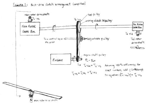
Although clutches vary with model, the two most common are the belt-driven and centrifugal arrangements. As for example, in the R22 helicopter from Robinson, the clutch arrangement is belt-driven. In this arrangement, mainly seen on small helicopters, the pulley on the engine shaft is connected to a pulley on the driving shaft going to the main rotor gear box and tail rotor gearbox. See Figure 1. In all, there are six pulleys and belts side-by-side. The belts are loosely fitted around the engine and driving shaft pulleys. In order to make the engine shaft pulley drive the top pulley, the pilot of the helicopter has to move an adjustable pulley, called the idler, and push it against the belts. This in turn tightens the belt and allows the engine shaft pulley to drive the driving shaft. The adjustable pulley is pushed against the belts by a pilot-activated lever on older models or by an electric motor on newer ones.
On the top pulley, there is a sprag clutch. Whenever the engine shaft is driving the shaft in the top pulley, the rollers inside the clutch are forced to the outer drum and prevent the top pulley from exceeding engine shaft rpm. This clutch serves as a freewheeling unit. I.e. whenever the engine shaft starts spinning at a slower rpm than the main rotor shaft (ex. engine stops), the rollers inside the clutch move inward and allow the outer drum to rotate at a speed faster then the inner portion. This characteristic of the sprag clutch could allow a pilot to land a helicopter safely if the engine stalled or simply stopped functioning.
 |
| Figure 2 |
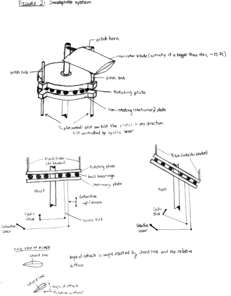
The collective and cyclic levers control the helicopter. These two control the motion of the swashplate system. See Figure 2. It consists of two plates separated by ball bearings. The top plate rotates freely. The bottom plate is a non-rotating plate and can move vertically and tilt in any direction. The pilot can affect the vertical position of the plates by moving the collective lever and the tilt through the cyclic lever. The cyclic control lever can tilt the swashplates in any direction. The rotating plate has pitch links connecting it to the pitch horns on the blade. This allows the rotating plate to change the angle of each blade. By adjusting the collective control lever, the pilot can move the stationary plate up and change the angle of attack of the blade. If it is increased (up to the stall angle), the helicopter rise.
 |
| Figure 3 |
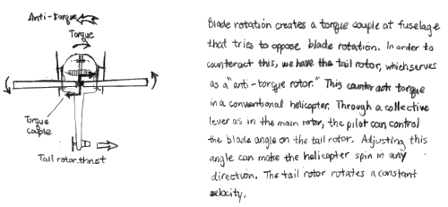
Something to notice is that the interaction between the rotating plate above the stationary plate creates a torque that causes the helicopter to spin opposite to the blades. On a conventional helicopter, this is where the tail rotor comes in. The tail rotor serves as an "anti-torque rotor" that counteracts the toque produced by the spinning rotating plate and blades. See Figure 3. To turn, the pilot either increases the angle of attack on the tail rotor blades to spin one way or decreases it to spin the other way.
[Miguel, the following will be deleted unless otherwise
requested, I do not see how it applies to the above]
To understand how the cyclic works, the concept of gyroscopic precession
needs to be understood. To simplify this, think of the blade rotation as a rotating disc.
Gyroscopic Precession simple states that if you have a rotating body, a disc in this case,
and a force is applied parallel to its axis of rotation, the disc's max tilt will occur
the direction of the force, 90 degrees after point where force is applied. See Figure 4.
In the helicopter's case, the direction of tilt of the swashplates will determine its
direction of motion.
DOMINANT PHYSICS:
See Figures
LIMITING PHYSICS:
None Submitted
PLOTS/GRAPHS/TABLES:
None Submitted
REFERENCES/MORE INFORMATION:
http://rebeca.mit.edu/helicopters
Interview: Kyrilian Dyer, MIT Undergraduate student, kyrilian@mit.edu
Principles Of Helicopter Flight by W.J. Wagtendonk
Schweizer: Helicopter Pilot Manual produced by JEPPESEN Sanderson Training Products