 |
|
| TAPE PLAYER DRIVE SYSTEM | ||
| QUESTIONS OR COMMENTS | ||
 |
AUTHOR: | Christina Park |
| E-MAIL: | sparky@mit.edu | |
| COURSE: | 2 | |
| CLASS/YEAR: | 1 | |
MAIN FUNCTIONAL REQUIREMENT: Vary the speed and direction of tape playing output shaft
DESIGN PARAMETER: Tape Player Gear Train
GEOMETRY/STRUCTURE:
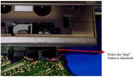 |
| Location of Function Buttons |
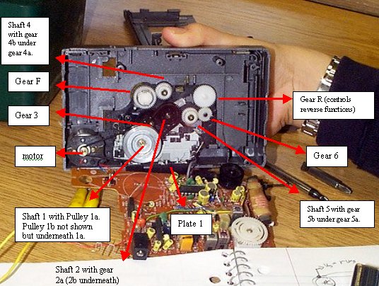 |
| Components of Tape Player Gear Train |
EXPLANATION OF HOW IT WORKS/ IS USED:
The tape player seen above consists of three basic parts: the function buttons, the plates (which are not all shown but underneath the gears and connected to them) and the gears. Each function is activated by a button, found on the outside. Pushing this button triggers a metal plate to move and engage certain gears. The three function buttons activate the motor, which powers the gear train.
Play:
The "play" function moves plate 1 to the left, setting the tape in motion by turning on the motor and putting power through its gear train of:
motor->belt->1a, 1b->belt->2a, 2a->3->F.
note: subscripts (a,b,....) denote 1 of multiple gears on the same shaft.
In this case, the motor gear (m) spins, and is connected by a belt to
pulley 1a, which spins shaft 1. Since the pulley 1b is on the same shaft, it spins with
the same rotational speed as gear 1a. Pulley 1b is also connected by a belt to pulley 2a.
Pulley 2a turns gear 3 directly, or "tooth-for-tooth", as gear 3 turns gear F,
the final gear. The final gear shaft turns the tape in the cassette. Note: This gear train
can vary from machine to machine.
Fast Forward:
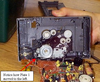
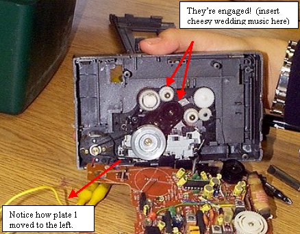
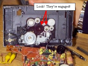
The "fast forward" function moves plate 1 to the left AND plate 2 forward (not shown). This engages gear 2 towards gear 4, changing the gear train to:
m->belt->1a, 1b->belt->2a, 2a->4a, 4b->F.
 |
| Gear Train Before Fast Forward Mode Engauged |
 |
| Gear Train After Fast Forward Mode Engauged |
Rewind:
Likewise, the "rewind" function moves plate 3 about 45 degrees NE of the play position, moving gear 2a to hit gear 5a. Thus the gear train is switched to:
m->belt->1a, 1b->belt->2a, 2a->5a, 5b->6->R.
 |
| Gear Train In Rewind |
DOMINANT PHYSICS:
Variable |
Description |
Metric Units |
English Units |
Vi |
Speed of belt i |
Meters/s |
inches/s |
Ri |
Pitch radius of gear i |
Meters |
inches |
wi |
Shaft rotational speed i |
Rad/s |
RPM |
Ni |
Number of teeth on gear i |
N/A |
N/A |
To calculate the rotational speed of a gear connected by a belt to another gear, we use the relation:
Vi = r ix wi.
The speed of the belt does not change, regardless of which gear it goes around, so
rmotor x wmotor = rgear 1a x wgear 1a.
For gears that connect "tooth-for-tooth", the rotational shaft speed is calculated using:
w1 x N1 = w2 x N2
To make this a little more tangible, I conducted a simple experiment. Using a digital tachometer (which displays the rotational speed of a rotating object), I took readings of the input and output w’s for each of the three functions, "play", "fast forward" and "rewind". I measured the radii of the pulleys connected by belts with a calibur. With the values of the radii and the number of teeth on gears, and the input rotational speed of the motor, I calculated the rotational speed of the output shaft. Then I compared these calculated values with the experimental values of the output rotational speed.
Note: The following analysis does not take into account the direction of spin, only speeds.
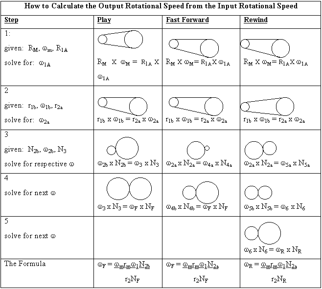
The formulas were can be calculated by using the relations shown above to solve for the rotational speed w at each step. I’ll do an example with "play":
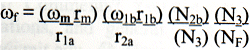
Some of the values cancel out, and you’re left with the formula shown above in the chart.
Note: Two gears on the same shaft have the same rotational speed, regardless of their sizes or number of teeth. This is the main idea behind the gear train: that the shaft will rotate at the same speed and the different size gears can "gear down" the train to make it slower, or "gear up" the train to make it faster. If two gears are different sizes, for example, if the small gear has 10 teeth and the big gear has 50 teeth, for every full turn the big gear makes, the small gear will turn 5 times. So if we connect a motor to the big gear and get it going, the small gear will output 5 times the number of rotations for a given time, making it faster. Likewise, if we connect the motor to the small gear, the big gear will only turn 1/5 the number of times the small gear turns, slowing the gear train down.
Since NF = NR and rf = rr, (the gears for fast forward and rewind are the same size and have the same number of teeth), they will spin at the same speed, but in opposite directions. When two gears are connected, either by belt or "tooth-for-tooth", they turn in opposite directions. For example, if the motor gear turns clockwise, the gear 1a will turn counter-clockwise. The rewind function has one more gear than the play or fast forward functions, so the direction the final shaft spins is opposite.
So for a given rotational speed of the motor, wm, I could calculate, using the formula I derived, the final rotational speed of the shaft that moves the cassette tape. I compared these values with that of the digital tachometer and they were within 5%, which can be accounted for by the measurement error of the pulley radii and the resolution of the tachometer.
LIMITING PHYSICS:
Since this device is powered by a battery, it is limited by how much power the battery puts out. The tape player that I disassembled required 3 AA batteries (about 1.5 volts each). I noticed that the shafts turned slower when using two batteries or even just one. All the measurements were taken using three batteries, which I assume maximizes the rotational speed without blowing the motor out.
There’s also the factor of friction between the teeth or the slip of the belt relative to the pulleys which reduces the power transferred between gears. (This can happen because the torque is limited as the belts slip.) You may notice some of this friction by the slight whirring noise that occurs when your tape player is in operation.
PLOTS/GRAPHS/TABLES:
None Submitted
WHERE TO FIND TAPE PLAYER GEAR TRAINS:
- Tape recorders
- Walkmen
- Microcassette recorders
- Answering Machines
- Gear trains are found everywhere!
REFERENCES/MORE INFORMATION:
None. The best part about this project is that it was done by taking a tape player and taking it apart. I didn’t use any books or references to find out how it works: just a little fiddling and some basic physics. No tape players were physically, emotionally, or mentally harmed as effects of my experiments, and have waived all rights to sue for damages.. Some wires were stripped to make connections to the batteries, but it’s ok, because they don’t feel violated.
Questions? Comments? You can email me at sparky@mit.edu with any praise, expressions of satisfaction, congratulations, and general "I’m impressed-isms". Complaints? You can email my instructor at mculpepp@mit.edu. J Have a nice day! J