Multiple Force Members
The term,
three-force member, is often incorrectly applied to members with
more than three forces. Any member which is subjected to the equivalent
of more than three single concentrated loads should be identified as a Multiple
Force Member. In order for this typical member to be resolved, the "extra"
forces acting upon a multiple force member must be replaced until the total
number of forces is reduced to three. Those three are the resultant force
of the loading and the two reactions. This implies that distributed loads
must always be replaced by equivalent concetrated loads, which are in turn
combined with all of the other forces until only one resultant force is
applied to the member. This then represents the external loading on the
member. The three non-parallel forces must be concurrent so that the three-force
principle can then be applied.

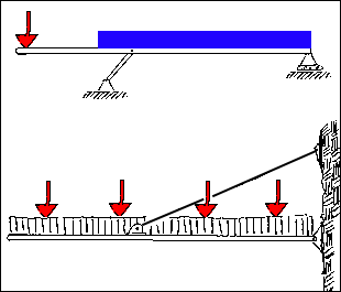
The illustrations are two examples of multiple force members:
The loading of the first image would be resolved in the following manner.
The resultant of the distributed load would be determined. This would act
at the mid-point of the width of the load. The resultant of this force and
the concentrated load acting at the cantilevered end of the beam would be
combined into one load by summing moments about the right-hand support.
This system would then be reduced from multiple force member to a three
force member.
The second system could represent an entrance canopy to a hotel that
also has four large spot lights sitting upon it. These six loads must also
be combined into one load resultant before the member can be considered
a three-force member. This is completed by :
- choosing a convenient point as the center of moments "O"
- find the total sum T of all of the forces
- determine the moment of each of the forces around point "O"
- determine the sum of these moments, M
- divide the sum M by T to determine the distance to the point of application
of T
- draw the equivalent load vector at this point
This is a typical method for combing any number of parallel loads. It
becomes very useful when loading combinations begin to be considered.
Questions for Thought
What multiple force members can you find in your daily routine? How would
the above process change if all of the loads were different....acting upward
for example? Would this method work if the beam was vertical?
Homework Problems
Additional Reading
none at this time
Copyright © 1995, 1996 by Chris H. Luebkeman and
Donald Peting
Copyright © 1997, 1998 by Chris H. Luebkeman


