

What is a Force?
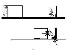 The one constant around the world is the action of gravity upon each
and every structure that is erected. The primary function of all structural
design is to make a building stand-up. Understanding architectonics will
enable a designer to include these issues as part of a design language that
will create a significantly clearer architectural expression. Primary to
this study is the concept of a force. A force is actually very abstract.
It can be defined, but it cannot become physically apparent until it meets
resistance. Imagine a six foot tall block of ice sliding along a frictionless
surface laid inside of a hockey rink. If a person props herself against
the wall and tries to stop the ice, she will perceive the force imparted
by the block of ice. She transfers the force of the block of ice into a
force that moves through her body into the ground. The ground resists her
with a force of varying magnitude to match her as she exerts an increasing
resistance force to stop the block of ice. If all of these forces are transferred
successfully, then the slide is arrested without a strength or stability
failure. However, if any one of the pieces of this fragile structural system
fail......
The one constant around the world is the action of gravity upon each
and every structure that is erected. The primary function of all structural
design is to make a building stand-up. Understanding architectonics will
enable a designer to include these issues as part of a design language that
will create a significantly clearer architectural expression. Primary to
this study is the concept of a force. A force is actually very abstract.
It can be defined, but it cannot become physically apparent until it meets
resistance. Imagine a six foot tall block of ice sliding along a frictionless
surface laid inside of a hockey rink. If a person props herself against
the wall and tries to stop the ice, she will perceive the force imparted
by the block of ice. She transfers the force of the block of ice into a
force that moves through her body into the ground. The ground resists her
with a force of varying magnitude to match her as she exerts an increasing
resistance force to stop the block of ice. If all of these forces are transferred
successfully, then the slide is arrested without a strength or stability
failure. However, if any one of the pieces of this fragile structural system
fail......Primary to the study of architectonics is the concept of forces. If the shape (its form) or motion (translation/rotation) of a body (structure, structural element) has been altered, a force has made that change. The shape of a plank changes when a person stands on it. A sailboat moves if wind hits the sail. The changes in shape and position are due to forces.Forces generally arise when two or more bodies interact. These bodies can be completely physical (plank and person), or more abstract (sail and wind). Forces can be represented graphically or mathematically as vectors quantities. Vector quantities indicate magnitude and direction, as opposed to Scalar quantities which indicate only magnitude.
Given a single force, one is interested in knowing all of the following:
1. Point of Application
2. Magnitude
3. Line of Action
4. Sense
Point of Application
The point of application is the exact location at which a force is applied
to a body. This point is usually described by a set of coordinates and is
represented graphically by the tip of the arrowhead. The point of application
is unique to each force. The point and the force cannot move. If several
forces of equal magnitude are present in a given situation, the forces are
unique based open the point of application, the line of action and their
sense. It can happen that forces of equal magnitude share the same point
of application, in this case, the line of action and sense determine their
uniqueness.
Magnitude
It is common to express the Magnitude of a force in units of pounds (lbs),
kips (kilo-pounds; 1 kip = 1000 lbs), newtons (N), or kilo-newtons (KN;
1 KN = 1000 N)). The Magnitude can be represented graphically by drawing
a vector to scale. Drawing the magnitude of these vectors accurately is
the essence of the method of Graphic Statics.
Line of Action
A force can be seen as a segment of an indefinitely long line. To each force
is associated a characteristic line, which is referred to as its line
of action. A reference axis is used in order to describe the orientation
of this line. The Figure shows that a line of action can be described in
terms of angle and slope.Translation results when a force attempts to move
the body along its line of action. (Benjamin) If the line of action of a
force does not pass through the body, then the force attempts to rotate
the body. This introduces the concept of Moments which will be discussed
soon.
Sense
The sense of a force specifies the direction (positive or negative) in which
the force moves along the line of action. Graphically, the sense can be
represented by an arrowhead pointing in the active direction. It is important
to always keep track of the sense of forces and that the convention used
for attaching a given sign remains consistent. The sense and direction can
be either a written verbal description (i.e. down and to the right, up and
to the left, slightly up and to the right ) or more conveniently expressed
in terms of 360 degrees (i.e. 112 degrees, 273 degrees, 87.5 degrees). In
the later case, one begins with zero and increases clock-wise with the direction
of the arrowhead until 360 is reached.
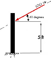
The direction always relates to the line of action of the vector, and the
sense is the way in which the vector would move along that line. In the
example, the direction and sense of the 100 lb force would be "down
and to the left" or "240 degrees."
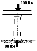 A 100 pound force
is applied to the stone column in the diagram. The colum will experience
this force at every point along the line of action of the force. As a matter
of fact, the force will also be transferred to the ground which is supporting
the column. Thus, the earth below the column along the line of action of
the force will also experience the 100 kip load. This illustrates the Principle
of Transmissibility. The point of application of an external force acting
on a body (structure) may be transmitted anywhere along the force's line
of action without affecting the other external forces (reactions and loads)
acting on that body. This means that there is NO NET CHANGE in the static
effect upon any body if the body is in equilibrium. This can be further
illustrated with the following diagram.
With means with which to describe forces, we can now look at the types
of forces which can exist in a structural system. Forces or Moments which
are applied directly to a structure are described as being external.
Reactive Forces are generated at locations where two or more bodies
meet (connections and supports) and are a direct result of the applied external
forces. (Newton's 3rd Law: For every action there is an equal and opposite
reaction) Forces or Moments which develop within a structure in response
to external forces are described as internal.
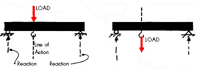
Assume that a beam is supported at its ends. A load is applied to the top of the beam that is acting downward. This load could be a person standing on the beam. The load creates reactions that push up at the two points of support. The line of action of the load (person) on the beam also passes through a hook that is attached to the underside of the beam. Now, if the person standing on top of the beam would climb down and hold on to the hook exactly below the point where they were previously located so that the lines of action were exactly the same, the reactions at the ends of the beams would not change. This is because the load of the person is still acting along the same line of action. As long as a load is applied at any point along the line of action the external reactions will not change.
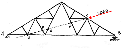
The truss above is loaded with a force that is applied at point C. This load creates reactions at the two supports A and B. The load on the truss could move anywhere along the line of action and the external reactions at A and B would remain the same. That means that if the load was applied at points D, E, F or G the reactions at A and B would not change. Note that the only point of discussion at this moment is the fact that the external reactions will not change. It is clear that the internal forces will vary greatly within the truss as the force is moved along the line of action. This issue will be discussed in a later lecture.
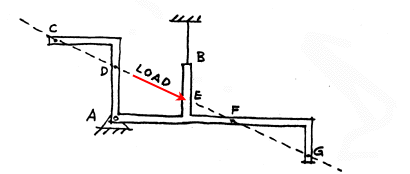
This strangly shaped beam is another example of a structure that is loaded at a specific point, namely E. In order for the structure to remain at rest there must be reactions of some kind at points A and B. The reaction at B is a tension reaction since it is a cable. Again, if the load was applied at points C, D, E, F or G on this rigid body (structure) the reactions at A and at B would remain exactly the same.
ONLY the EXTERNAL forces (reactions) remain unchanged. Some of the internal resisting forces within the elements of the structure change as the load is applied at different points along its line of action. This illustrates one important difference between INTERNAL and EXTERNAL forces.
The Principle of Transmissibility applies to any body (blobs, balloons, simple beams, crooked beams, trusses, shells, etc.). It is independent of the body's size or shape.
What happens to the reactions at A and B if the sense of the applied load would be reversed in both of preceeding diagrams?
Schodek. pp. 30 - 35.