
13.5
Dielectric Waveguides: Optical Fibers
Waves can be guided by dielectric rods or slabs and the fields of these waves occupy the space within and around these dielectric structures. Especially at optical wavelengths, dielectric fibers are commonly used to guide waves. In this section, we develop the properties of waves guided by a planar sheet of dielectric material. The waves that we find are typical of those found in integrated optical systems and in the more commonly used optical fibers of circular cross-section.
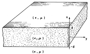
A planar version of a dielectric waveguide is pictured in Fig. 13.5.1. A dielectric of thickness 2d and permittivity
i is surrounded by a dielectric of permittivity
<
i. The latter might be free space with
=
o. We are interested in how this structure might be used to guide waves in the y direction and will confine ourselves to fields that are independent of z.
Figure 13.5.1 Dielectric slab waveguide. With a source somewhere to the left (for example an antenna imbedded in the dielectric), there is reason to expect that there are fields outside as well as inside the dielectric. We shall look for field solutions that propagate in the y direction and possess fields solely inside and near the layer. The fields external to the layer decay to zero in the
x directions. Like the waves propagating along waveguides, those guided by this structure have transverse components that take the form
both inside and outside the dielectric. That is, the fields inside and outside the dielectric have the same frequency
, the same phase velocity
/ky, and hence the same wavelength 2
/ky in the y direction. Of course, whether such fields can actually exist will be determined by the following analysis.
The classification of two-dimensional fields introduced in Sec. 12.6 is applicable here. The TM and TE fields can be made to independently satisfy the boundary conditions so that the resulting modes can be classified as TM or TE.
10 Circular dielectric rods do not support simple TE or TM waves; in that case, this classification of modes is not possible.
Here we will confine ourselves to the transverse electric modes. In the exterior and interior regions, where the permittivities are uniform but different, it follows from substitution of (1) into (12.6.33) (Table 12.8.3) that
A guided wave is one that is composed of a nonuniform plane wave in the exterior regions, decaying in the
x directions and propagating with the phase velocity
/ky in the y direction. In anticipation of this, we have written (2) in terms of the parameter
x, which must then be real and positive. Through the continuity conditions, the exterior wave must match up to the interior wave at the dielectric surfaces. The solutions to (3) are sines and cosines if kx is real. In order to match the interior fields onto the nonuniform plane waves on both sides of the guide, it is necessary that kx be real.
We now set out to find the wave numbers ky that not only satisfy the wave equations in each of the regions, represented by (2) and (3), but the continuity conditions at the interfaces as well. The configuration is symmetric about the x = 0 plane so we can further divide the modes into those that have even and odd functions Ez (x). Thus, with A an arbitrary factor, appropriate even solutions to (2) and (3) are
To simplify the algebra, we have displaced the origin in the exterior solutions so that just the coefficient, A, is obtained when
z is evaluated at the respective interfaces. With a similar objective, the interior solution has been divided by the constant cos (kx d) so that at the boundaries,
z also becomes A. In this way, we have adjusted the interior coefficient so that
z is continuous at the boundaries.
Because this transverse field is the only component of E, all of the continuity conditions on E are now satisfied. The permeabilities of all regions are presumed to be the same, so both tangential and normal components of H must be continuous at the boundaries. From (12.6.29), the continuity of normal
H is guaranteed by the continuity of Ez in any case. The tangential field is obtained using (12.6.30).
Substitution of (4) into (5) gives
The assumption that Ez is even in x has as a consequence the fact that the continuity condition on tangential H is satisfied by the same relation at both boundaries.
Our goal is to determine the propagation constant ky for a given
. If we were to substitute the definitions of
x and kx into this expression, we would have this dispersion equation, D(
,ky), implicitly relating ky to
. It is more convenient to solve for
x and kx first, and then for ky.
Elimination of ky between the expressions for
x and kx given with (2) and (3) gives a second expression for
x /kx.
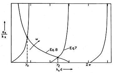
The solutions for the values of the normalized transverse wave numbers (kx d) can be pictured as shown in Fig. 13.5.2. Plotted as functions of kx d are the right-hand sides of (7) and (8). The points of intersection, kx d =
m, are the desired solutions. For the frequency used to make Fig. 13.5.2, there are two solutions. These are designated by even integers because the odd modes (Prob. 13.5.1) have roots that interleave these even modes.
Figure 13.5.2 Graphical solution to (7) and (8). As the frequency is raised, an additional even TE-guided mode is found each time the curve representing (8) reaches a new branch of (7). This happens at frequencies
c such that
x /kx = 0 and kx d = m
/2, where m = 0, 2, 4,
From (8),
The m = 0 mode has no cutoff frequency.
To finally determine ky from these eigenvalues, the definition of kx given with (3) is used to write
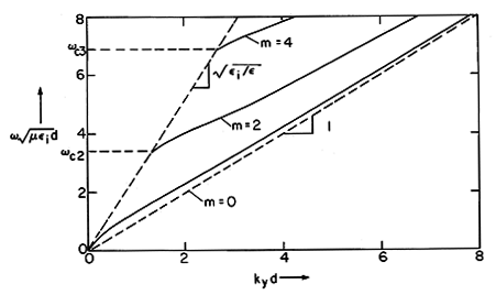
and the dispersion equation takes the graphical form of Fig. 13.5.3. To make Fig. 13.5.2, we had to specify the ratio of permittivities, so that ratio is also implicit in Fig. 13.5.3.
Figure 13.5.3 Dispersion equation for even TE modes with i /
= 6.6.
Features of the dispersion diagram, Fig. 13.5.3, can be gathered rather simply. Where a mode is just cutoff because
=
c,
x = 0, as can be seen from Fig. 13.5.2. From (2), we gather that ky =
c
. Thus, at cutoff, a mode must have a propagation constant ky that lies on the straight broken line to the left, shown in Fig. 13.5.3. At cutoff, each mode has a phase velocity equal to that of a plane wave in the medium exterior to the layer.
In the high-frequency limit, where
goes to infinity, we see from Fig. 13.5.2 that kxd approaches the constant kx
(m + 1)
/2d. That is, in (3), kx becomes a constant even as
goes to infinity and it follows that in this high frequency limit ky

i.
The physical reasons for this behavior follow from the nature of the mode pattern as a function of frequency. When
x
0, as the frequency approaches cutoff, it follows from (4) that the fields extend far into the regions outside of the layer. The wave approaches an infinite parallel plane wave having a propagation constant that is hardly affected by the layer. In the opposite extreme, where
goes to infinity, the decay of the external field is rapid, and a given mode is well confined inside the layer. Again, the wave assumes the character of an infinite parallel plane wave, but in this limit, one that propagates with the phase velocity of a plane wave in a medium with the dielectric constant of the layer.
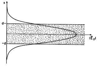
The distribution of Ez of the m = 0 mode at one frequency is shown in Fig. 13.5.4. As the frequency is raised, each mode becomes more confined to the layer.
Figure 13.5.4 Distribution of transverse E for TE0 mode on dielectric waveguide of Fig. 13.5.1.
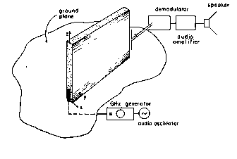
Demonstration 13.5.1. Microwave Dielectric Guided Waves
In the experiment shown in Fig. 13.5.5, a dielectric slab is demonstrated to guide microwaves. To assure the excitation of only an m = 0 TE-guided wave, but one as well confined to the dielectric as possible, the frequency is made just under the cutoff frequency
c2. (For a 2 cm thick slab having
i /
o = 6.6, this is a frequency just under 6 GHz.) The m = 0 wave is excited in the dielectric slab by means of a vertical element at its left edge. This assures excitation of Ez while having the symmetry necessary to avoid excitation of the odd modes.
Figure 13.5.5 Dielectric waveguide demonstration. The antenna is mounted at the center of a metal ground plane. Thus, without the slab, the signal at the receiving antenna (which is oriented to be sensitive to Ez) is essentially the same in all directions perpendicular to the z axis. With the slab, a sharply increased signal in the vicinity of the right edge of the slab gives qualitative evidence of the wave guidance. The receiving antenna can also be used to probe the field decay in the x direction and to see that this decay increases with frequency.
11To make the excitation independent of z, a collinear array of in-phase dipoles could be used for the excitation. This is not necessary to demonstrate the qualitative features of the guide.
