
1.4
Ampère's Integral Law
The law relating the magnetic field intensity H to its source, the current density J, is
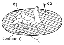
Note that by contrast with the integral statement of Gauss' law, (1.3.1), the surface integral symbols on the right do not have circles. This means that the integrations are over open surfaces, having edges denoted by the contour C. Such a surface S enclosed by a contour C is shown in Fig. 1.4.1. In words, Ampère's integral law as given by (1) requires that the line integral (circulation) of the magnetic field intensity H around a closed contour is equal to the net current passing through the surface spanning the contour plus the time rate of change of the net displacement flux density
o E through the surface (the displacement current).
Figure 1.4.1. Surface S is enclosed by contour C having positive direction determined by the right-hand rule. With the fingers in the direction of ds, the thumb passes through the surface in the direction of positive da. The direction of positive da is determined by the right-hand rule, as also illustrated in Fig. 1.4.1. With the fingers of the right-hand in the direction of ds, the thumb has the direction of da. Alternatively, with the right hand thumb in the direction of ds, the fingers will be in the positive direction of da.
In Ampère's law, H appears without
o. This law therefore establishes the basic units of H as coulomb/(meter-second). In Sec. 1.1, the units of the flux density
o H are defined by the Lorentz force, so the second empirical constant, the permeability of free space, is
o = 4
x 10-7 henry/m (henry = volt sec/amp).
Example 1.4.1. Magnetic Field Due to Axisymmetric Current
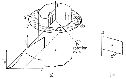
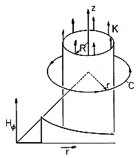
A constant current in the z direction within the circular cylindrical region of radius R, shown in Fig. 1.4.2, extends from - infinity to + infinity along the z axis and is represented by the density
where Jo and R are given constants. The associated magnetic field intensity has only an azimuthal component.
Figure 1.4.2. Axially symmetric current distribution and associated radial distribution of azimuthal magnetic field intensity. Contour C is used to determine azimuthal H, while C' is used to show that the z-directed field must be uniform. To see that there can be no r component of this field, observe that rotation of the source around the radial axis, as shown in Fig. 1.4.2, reverses the source (the current is then in the -z direction) and hence must reverse the field. But an r component of the field does not reverse under such a rotation and hence must be zero. The H
and Hz components are not ruled out by this argument. However, if they exist, they must not depend upon the
and z coordinates, because rotation of the source around the z axis and translation of the source along the z axis does not change the source and hence does not change the field.
The current is independent of time and so we assume that the fields are as well. Hence, the last term in (1), the displacement current, is zero. The law is then used with S, a surface having its enclosing contour C at the arbitrary radius r, as shown in Fig. 1.4.2. Then the area and line elements are
and the right-hand side of (1) becomes
Integration on the left-hand side amounts to a multiplication of the
independent H
by the length of C.
These last two expressions are used to evaluate (1) and obtain
Thus, the azimuthal magnetic field intensity has the radial distribution shown in Fig. 1.4.2.
The z component of H is, at most, uniform. This can be seen by applying the integral law to the contour C', also shown in Fig. 1.4.2. Integration on the top and bottom legs gives zero because Hr = 0. Thus, to make the contributions due to Hz on the vertical legs cancel, it is necessary that Hz be independent of radius. Such a uniform field must be caused by sources at infinity and is therefore set equal to zero if such sources are not postulated in the statement of the problem.
Singular Current Distributions
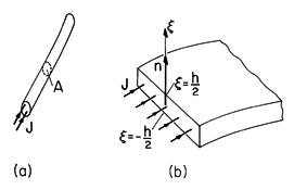
The first of two singular forms of the current density shown in Fig. 1.4.3a is the line current. Formally, it is the limit of an infinite current density distributed over an infinitesimal area.
With i a constant over the length of the line, a thin wire carrying a current i conjures up the correct notion of the line current. However, in general, the current i may depend on the position along the line if it varies with time as in an antenna.
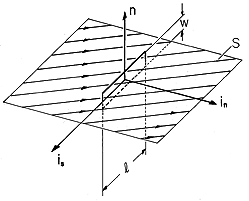
Figure 1.4.3. (a) Line current enclosed by volume having cross-sectional area A. (b) Surface current density enclosed by contour having thickness h. The second singularity, the surface current density, is the limit of a very large current density J distributed over a very thin layer adjacent to a surface. In Fig. 1.4.3b, the current is in a direction parallel to the surface. If the layer extends between
= -h/2 and
= +h/2, the surface current density K is defined as
By definition, K is a vector tangential to the surface that has units of ampere/meter.
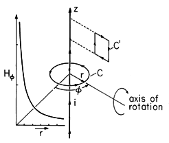
Figure 1.4.4. Uniform line current with contours for determining H. Axis of rotation is used to deduce that radial component of field must be zero.
Illustration. H field Produced by a Uniform Line Current
A uniform line current of magnitude i extends from - infinity to + infinity along the z axis, as shown in Fig. 1.4.4. The symmetry arguments of Example 1.4.1 show that the only component of H is azimuthal. Application of Ampère's integral law, (1), to the contour of Fig. 1.4.4 having arbitrary radius r gives a line integral that is simply the product of H
and the circumference 2
r and a surface integral that is simply i, regardless of the radius.
This expression makes it especially clear that the units of H are ampere/meter.
Demonstration 1.4.1. Magnetic Field of a Line Current
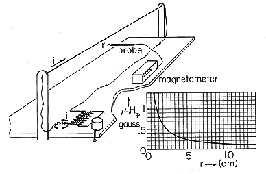
At 60 Hz, the displacement current contribution to the magnetic field of the experiment shown in Fig. 1.4.5 is negligible. So long as the field probe is within a distance r from the wire that is small compared to the distance to the ends of the wire or to the return wires below, the magnetic field intensity is predicted quantitatively by (10). The curve shown is typical of demonstration measurements illustrating the radial dependence. Because the Hall-effect probe fundamentally exploits the Lorentz force law, it measures the flux density
oH. A common unit for flux density is the Gauss. For conversion of units, 10,000 gauss = 1 tesla, where the tesla is the SI unit.
Figure 1.4.5. Demonstration of peak magnetic flux density induced by line current of 6 ampere (peak).
Illustration. Uniform Axial Surface Current
At the radius R from the z axis, there is a uniform z directed surface current density Ko that extends from - infinity to + infinity in the z direction. The symmetry arguments of Example 1.4.1 show that the resulting magnetic field intensity is azimuthal. To determine that field, Ampère's integral law is applied to a contour having the arbitrary radius r, shown in Fig. 1.4.6. As in the previous illustration, the line integral is the product of the circumference and H
. The surface integral gives nothing if r < R, but gives 2
R times the surface current density if r > R. Thus,
Figure 1.4.6. Uniform current density Ko is z directed in circular cylindrical shell at r = R. Radially discontinuous azimuthal field shown is determined using the contour at arbitrary radius r.
Thus, the distribution of H
is the discontinuous function shown in Fig. 1.4.6. The field tangential to the surface current undergoes a jump that is equal in magnitude to the surface current density.

