
10.4
Diffusion of Transverse Magnetic FieldsThrough Thin Conductors
In this section we study magnetic induction of currents in thin conducting shells by fields transverse to the shells. In Sec. 10.3, the magnetic fields were automatically tangential to the conductor surfaces, so we did not have the opportunity to explore the limitations of the boundary condition n
B = 0 used to describe a "perfect conductor." In this section the imposed fields generally have components normal to the conducting surface.
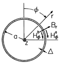
Figure 10.4.1 Cross-section of circular cylindrical conducting shell having its axis perpendicular to the magnetic field. The steps we now follow can be applied to many different geometries. We specifically consider the circular cylindrical shell shown in cross-section in Fig. 10.4.1. It has a length in the z direction that is very large compared to its radius a. Its conductivity is
, and it has a thickness
that is much less than its radius a. The regions outside and inside are specified by (a) and (b), respectively.
The fields to be described are directed in planes perpendicular to the z axis and do not depend on z. The shell currents are z directed. A current that is directed in the +z direction at one location on the shell is returned in the -z direction at another. The closure for this current circulation can be imagined to be provided by perfectly conducting endplates, or by a distortion of the current paths from the z direction near the cylinder ends (end effect).
The shell is assumed to have essentially the same permeability as free space. It therefore has no tendency to guide the magnetic flux density. Integration of the magnetic flux continuity condition over an incremental volume enclosing a section of the shell shows that the normal component of B is continuous through the shell.
Ohm's law relates the axial current density to the axial electric field, Jz =
Ez. This density is presumed to be essentially uniformly distributed over the radial cross-section of the shell. Multiplication of both sides of this expression by the thickness
of the shell gives an expression for the surface current density in the shell.
Faraday's law is a vector equation. Of the three components, the radial one is dominant in describing how the time-varying magnetic field induces electric fields, and hence currents, tangential to the shell. In writing this component, we assume that the fields are independent of z.
Ampère's continuity condition makes it possible to express the surface current density in terms of the tangential fields to either side of the shell.
These last three expressions are now combined to obtain the desired continuity condition.
Thus, the description of the shell is encapsulated in the two continuity conditions, (1) and (5).
The thin-shell model will now be used to place in perspective the idealized boundary condition of perfect conductivity. In the following example, the conductor is subjected to a field that is suddenly turned on. The field evolution with time places in review the perfect conductivity mode of MQS systems in Chap. 8 and the magnetization phenomena of Chap. 9. Just after the field is turned on, the shell acts like the perfect conductors of Chap. 8. As time goes on, the shell currents decay to zero and only the magnetization of Chap. 9 persists.
Example 10.4.1. Diffusion of Transverse Field into Circular Cylindrical Conducting Shell with a Permeable Core
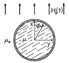
A permeable circular cylindrical core having radius a is shown in Fig. 10.4.2. It is surrounded by a thin conducting shell, having thickness
and conductivity
. A uniform time-varying magnetic field intensity Ho (t) is imposed transverse to the axis of the shell and core. The configuration is long enough in the axial direction to justify representing the fields as independent of the axial coordinate z.
Figure 10.4.2 Circular cylindrical conducting shell filled by insulating material of permeability and surrounded by free space. A magnetic field Ho(t) that is uniform at infinity is imposed transverse to the cylinder axis.
Reflecting the fact that the region outside (o) is free space while that inside (i) is the material of linear permeability are the constitutive laws
For the two-dimensional fields in the r -
plane, where the sheet current is in the z direction, the scalar potential provides a convenient description of the field.
We begin by recognizing the form taken by
far from the cylinder.
Note that substitution of this relation into (7) indeed gives the uniform imposed field.
Given the
dependence of (8), we assume solutions of the form
where A and C are coefficients to be determined by the continuity conditions. In preparation for the evaluation of these conditions, the assumed solutions are substituted into (7) to give the flux densities
Should we expect that these functions can be used to satisfy the continuity conditions at r = a given by (1) and (5) at every azimuthal position
? The inside and outside radial fields have the same
dependence, so we are assured of being able to adjust the two coefficients to satisfy the flux continuity condition. Moreover, in evaluating (5), the
derivative of H
has the same
dependence as Br. Thus, satisfying the continuity conditions is assured.
The first of two relations between the coefficients and Ho follows from substituting (10) into (1).
The second results from a similar substitution into (5).
With C eliminated from this latter equation by means of (11), we obtain an ordinary differential equation for A(t).
The time constant
m takes the form of (10.2.7).
In (13), the time dependence of the imposed field is arbitrary. The form of this expression is the same as that of (7.9.28), so techniques for dealing with initial conditions and for determining the sinusoidal steady state response introduced there are directly applicable here.
Response to a Step in Applied Field
Suppose there is no field inside or outside the conducting shell before t = 0 and that Ho is a step function of magnitude Hm turned on when t = 0. With D a coefficient determined by the initial condition, the solution to (13) is the sum of a particular and a homogeneous solution.
Integration of (13) from t = 0- to t = 0+ shows that A(0) = - Hm a2, so that D is evaluated and (15) becomes
This expression makes it possible to evaluate C using (11). Finally, these coefficients are substituted into (9) to give the potential outside and inside the shell.
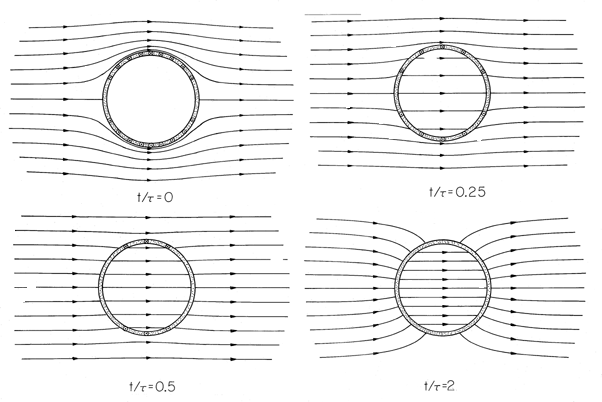
Figure 10.4.3 When t = 0, a magnetic field that is uniform at infinity is suddenly imposed on the circular cylindrical conducting shell. The cylinder is filled by an insulating material of permeability = 200
o. When t/
= 0, an instant after the field is applied, the surface currents completely shield the field from the central region. As time goes on, these currents decay, until finally the field is no longer influenced by the conducting shell. The final field is essentially perpendicular to the highly permeable core. In the absence of this core, the final field would be uniform.
The field evolution represented by these expressions is shown in Fig. 10.4.3, where lines of B are portrayed. When the transverse field is suddenly turned on, currents circulate in the shell in such a direction as to induce a field that bucks out the one imposed. For an applied field that is positive, this requires that the surface current be in the -z direction on the right and returned in the +z direction on the left. This surface current density can be analytically expressed first by using (10) to evaluate Ampère's continuity condition
and then by using (15).
With the decay of Kz, the external field goes from that for a perfect conductor (where n
B = 0) to the field that would have been found if there were no conducting shell. The magnetizable core tends to draw this field into the cylinder.
The coefficient A represents the amplitude of a two-dimensional dipole that has a field equivalent to that of the shell current. Just after the field is applied, A is negative and hence the equivalent dipole moment is directed opposite to the imposed field. This results in a field that is diverted around the shell. With the passage of time, this dipole moment can switch sign. This sign reversal occurs only if
>
o, making it clear that it is due to the magnetization of the core. In the absence of the core, the final field is uniform.
Under what conditions can the shell be regarded as perfectly conducting? The answer involves not only
but also the time scale and the size, and to some extent, the permeability. For our step response, the shell shields out the field for times that are short compared to
m, as given by (14).
Demonstration 10.4.1. Currents Induced in a Conducting Shell
The apparatus of Demonstration 10.2.1 can be used to make evident the shell currents predicted in the previous example. A cylinder of aluminum foil is placed on the driver coil, as shown in Fig. 10.4.4. With the discharge of the capacitor through the coil, the shell is subjected to an abruptly applied field. By contrast with the step function assumed in the example, this field oscillates and decays in a few cycles. However, the reversal of the field results in a reversal in the induced shell current, so regardless of the time dependence of the driving field, the force density J x B is in the same direction.
Figure 10.4.4 In an experiment giving evidence of the currents induced when a field is suddenly applied transverse to a conducting cylinder, an aluminum foil cylinder, subjected to the field produced by the experiment of Fig. 10.2.2, is crushed. The force associated with the induced current is inward. If the applied field were truly uniform, the shell would then be "squashed" inward from the right and left by the field. Because the field is not really uniform, the cylinder of foil is observed to be compressed inward more at the bottom than at the top, as suggested by the force vectors drawn in Fig. 10.4.4. Remember that the postulated currents require paths at the ends of the cylinder through which they can circulate. In a roll of aluminum foil, these return paths are through the shell walls in those end regions that extend beyond the region of the applied field.
The derivation of the continuity conditions for a circular cylindrical shell follows a format that is applicable to other geometries. Examples are a planar sheet and a spherical shell.


