
10.5
Magnetic Diffusion Laws
The self-consistent evolution of the magnetic field intensity H with its source J induced in Ohmic materials of finite conductivity is familiar from the previous two sections. In the models so far considered, the induced currents were in thin conducting shells. Thus, in the processes of magnetic relaxation described in these sections, the currents were confined to thin regions that could be represented by dynamic continuity conditions.
In this and the next two sections, the conductor extends throughout at least part of a volume of interest. Like H, the current density in Ampère's law
is an unknown function. For an Ohmic material, it is proportional to the local electric field intensity.
In turn, E is induced in accordance with Faraday's law
The conductor is presumed to have uniform conductivity
and permeability
. For linear magnetization, the magnetic flux continuity law is
In the MQS approximation the current density J is also solenoidal, as can be seen by taking the divergence of Ampère's law.
In the previous two sections, we combined the continuity conditions implied by (1) and (4) with the other laws to obtain dynamic continuity conditions representing thin conducting sheets. The regions between sheets were insulating, and so the field distributions in these regions were determined by solving Laplace's equation. Here we combine the differential laws to obtain a new differential equation that takes on the role of Laplace's equation in determining the distribution of magnetic field intensity.
If we solve Ohm's law, (2), for E and substitute for E in Faraday's law, we have in one statement the link between magnetic induction and induced current density.
The current density is eliminated from this expression by using Ampère's law, (1). The result is an expression of H alone.
This expression assumes a somewhat more familiar appearance when
and
are constants, so that they can be taken outside the operations. Further, it follows from (4) that H is solenoidal so the use of a vector identity
H
=
(

H) -
2 H turns (7) into
At each point in a material having uniform conductivity and permeability, the magnetic field intensity satisfies this vector form of the diffusion equation. The distribution of current density implied by the H found by solving this equation with appropriate boundary conditions follows from Ampère's law, (1).
Physical Interpretation
With the understanding that H and J are solenoidal, the derivation of (8) identifies the feedback between source and field that underlies the magnetic diffusion process. The effect of the (time-varying) field on the source embodied in the combined laws of Faraday and Ohm, (6), is perhaps best appreciated by integrating (6) over any fixed open surface S enclosed by a contour C. By Stokes' theorem, the integration of the curl over the surface transforms into an integration around the enclosing contour. Thus, (6) implies that
and requires that the electromotive force around any closed path must be equal to the time rate of change of the enclosed magnetic flux. Numerical approaches to solving magnetic diffusion problems may in fact approximate a system by a finite number of circuits, each representing a current tube with its own resistance and flux linkage. To represent the return effect of the current on H, the diffusion equation also incorporates Ampère's law, (1).
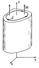
Figure 10.5.1 Configurations in which cylindrically shaped conductors having axes parallel to the magnetic field have currents transverse to the field in x-y planes. The relaxation of axial fields through thin shells, developed in Sec. 10.3, is an example where the geometry of the conductor and the symmetry make the current tubes described by (9) readily discernible. The diffusion of an axial magnetic field Hz into the volume of cylindrically shaped conductors, as shown in Fig. 10.5.1, is a generalization of the class of axial problems described in Sec. 10.3. As the only component of H , Hz (x, y) must satisfy (8).
The current density is then directed transverse to this field and given in terms of Hz by Ampère's law.
Thus, the current density circulates in x - y planes.
Methods for solving the diffusion equation are natural extensions of those used in previous chapters for dealing with Laplace's equation. Although we confine ourselves in the next two sections to diffusion in one spatial dimension, the thin-shell models give an intuitive impression as to what can be expected as magnetic fields diffuse into solid conductors having a wide range of geometries.
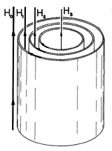
Figure 10.5.2 Example of an axial field configuration composed of coaxial conducting shells of infinite axial length. When an exterior field Ho is applied, currents circulating in the shells tend to shield out the imposed field. Consider the coaxial thin shells shown in Fig. 10.5.2 as a model for a solid cylindrical conductor. Following the approach outlined in Sec. 10.3, suppose that the exterior field Ho is an imposed function of time. Then the fields between sheets (H1 and H2) and in the central region (H3) are determined by a system of three ordinary differential equations having Ho (t) as a drive. Associated with the evolution of these fields are surface currents in the shells that tend to shield the field from the region within. In the limit where the number of shells is infinite, the field distribution in a solid conductor could be represented by such coupled thin shells. However, the more practical approach used in the next sections is to solve the diffusion equation exactly. The situations considered are in cartesian rather than polar coordinates.


