Introduction
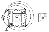
| (a) | Show that the voltage measured with the positive lead connected at (1), so that the
voltmeter is across one of the resistors, is v = (d  /dt)/4.
|
| (b) | Show that if the positive voltmeter lead is connected to (2), then to (3), and finally to (4) (so that the lead is wrapped around the core once and connected to the same grounded node as the negative voltmeter lead), the voltages are, respectively, twice, three times, and four times this value. Show that this last result is as would be expected for a transformer with a one-turn secondary. |
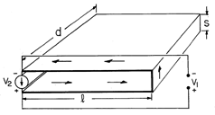
| (a) | Given that d and l are much greater than the spacing s, determine the voltage measured across the terminals of the current source by the voltmeter v2. |
| (b) | What is the voltage measured by the voltmeter v1 connected as shown in the figure across these same terminals? |
Magnetoquasistatic Electric Fields in Systems of Perfect Conductors

 a
a  w.
w.
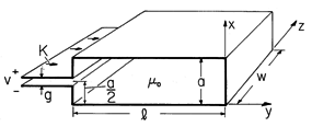
| (a) | In terms of K(t), what is H between the plates? |
| (b) | Determine a
particular solution having the form Ep = ix Exp (y,
t), and find E.
|
 = 0,
= 0,
 =
=  , and r = a.
The latter is broken at the middle and driven by
a current source of K(t) amps/unit length in the z direction. The
current circulates around the perfectly conducting path provided by
the sheets, as shown in the figure. Assume that the angle

 and that the system is long enough in the z direction
to justify taking the fields as two dimensional.
| (a) | In terms of K(t), what is H in the pie-shaped region? |
| (b) | What is E in this region? |

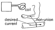
Because the material to be heated has a small conductivity, the
induced currents are small and contribute a magnetic field that is
small compared to that imposed. Thus, the approach to determining the
distribution of current induced in the semiconductor is 1) to first
find H, ignoring the effect of the induced current. This amounts
to solving Ampère's law and the flux continuity law with the current
density that of the excitation coil. Then, 2) with B known, the
electric field in the semiconductor is determined using Faraday's law
and the MQS form of the conservation of charge law, 
 (
( E) = 0. The approach to finding the fields can then
be similar to that illustrated in this section.
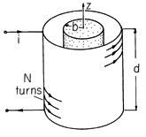
| (a) | Show that in the semiconductor and in the annulus, B
 ( ( o Ni/d) iz. o Ni/d) iz.
|
| (b) | Use the symmetry about the z
axis to show that in the semiconductor, where there is no radial
component of J and hence of E at r = b,
E = -( o Nr/2d)(di/dt)i o Nr/2d)(di/dt)i . .
|
| (c) | To investigate the
conditions under which this approximation is useful, suppose that the
excitation is sinusoidal, with angular frequency  . Approximate
the magnetic field intensity Hinduced associated with the induced
current. Show that for the approximation to be good,
Hinduced/Himposed = . Approximate
the magnetic field intensity Hinduced associated with the induced
current. Show that for the approximation to be good,
Hinduced/Himposed =   o o  b2 /4 b2 /4  1. 1.
|
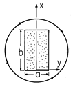
| (a) | In terms of the coordinates shown, find a particular solution for E that takes the form E = iy Eyp(x, t) and satisfies the boundary conditions at x = 0 and x = b. |
| (b) | Determine E inside the material of
rectangular cross-section.
|
| (c) | Sketch the particular, homogeneous, and total electric fields, making clear how the first two add up to satisfy the boundary conditions. (Do not take the time to evaluate your analytical formula but rather use your knowledge of the nature of the solutions and the boundary conditions that they must satisfy.) |
Nature of Fields Induced in Finite Conductors

 m
m  1, then the flux linked by the secondary
is small. In Example 9.7.4, it was shown that operation of a
transformer in its "ideal" mode also implies that the flux linked by
the secondary be small. There it was found that to achieve this
condition, the time constant L22/R of the secondary must be long
compared to times of interest. Approximate the inductance and
resistance of the disk in Fig. 10.2.3 and show that L22/R is
indeed roughly the same as the time given by (10.2.17).
 and radius a. Following steps parallel to those
represented by (10.2.13)-(10.2.16), show that Hind/H1 is
roughly
 m, where
  m is given by (10.3.10).
(Assume that the applied field is essentially uniform over the
dimensions of the shell.)
Diffusion of Axial Magnetic Fields through Thin Conductors
 and conductivity
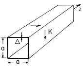
  is formed into a cylinder having a square cross-section, as shown in
Fig. P10.3.1. It is very long compared to its cross-sectional
dimensions a. When t = 0, there is a surface current density Ko
circulating uniformly around the shell. Show that the subsequent
surface current density is K(t) = Ko exp (-t/
 m) where
  m
=
m
=  o
o 
 a/4.
a/4.
 shown in cross-section by
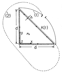
Fig. P10.3.2 forms a one-turn solenoid having length l that is
large compared to the length d of two of the sides of its
right-triangular cross-section. When t = 0, there is a circulating
current density Jo uniformly distributed in the conductor.
| (a) | Determine the surface current density K(t) =  J(t) for t > 0. J(t) for t > 0.
|
| (b) | A high-impedance voltmeter is connected as shown between the lower right and upper left corners. What v(t) is measured? |
| (c) | Now lead (1) is connected following path (2). What voltage is measured? |
 and radii a and b,
respectively.
| (a) | Show that the fields H1 and H2, between the shells and inside the inner shell, respectively, are governed by the
equations ( m = m =  o o   b/2) b/2)
  |
| (b) | Given that Ho = Hm cos  t, show that the
sinusoidal steady state fields are H1 = Re { [Hm (1 + j t, show that the
sinusoidal steady state fields are H1 = Re { [Hm (1 + j
 m )/D] exp j m )/D] exp j t} and H2 = Re { [Hm/D]
exp j t} and H2 = Re { [Hm/D]
exp j t} where D = [1 + j t} where D = [1 + j  m (a/b - b/a)](1 +
j m (a/b - b/a)](1 +
j  m ) + j m ) + j  m (b/a). m (b/a).
|
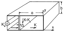
 -shaped perfect conductor shown in Fig. P10.3.4 is
driven along its left edge by a current source having the uniformly
distributed density Ko (t). At x = -a there is a thin sheet having
the nonuniform conductivity
  =
=  o /[1 +
  cos (
cos ( y/b)].
The length in the z direction is much greater than the other
dimensions.
| (a) | Given Ko (t), find a differential equation for K(t). |
| (b) | In terms of the solution K(t) to this equation, determine
E in the region -a < x < 0, 0 < y < b.
|
Diffusion of Transverse Magnetic Fields through Thin Conductors
 and thickness
  extends to infinity in the x and z directions, as shown in Fig.
P10.4.1. Currents in the sheet are z directed and independent of z.
| (a) | Show that the sheet can be represented by the boundary conditions
  |
| (b) | Now consider the special case where the regions above
and below are free space and extend to infinity in the +y and -y
directions, respectively. When t = 0, there is a surface current
density in the sheet K = iz Ko sin  x, where Ko and x, where Ko and
 are given constants. Show that for t > 0, Kz = Ko exp
(-t/ are given constants. Show that for t > 0, Kz = Ko exp
(-t/ ) where ) where  = =  o o   /2 /2 . .
|

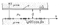
 and
thickness
  . This sheet is, in turn, backed by a material of
infinite permeability. The region below is also infinitely permeable
and at the interface y = 0 there is a winding used to impose the surface
current density K = K(t) cos
  x iz. The system extends to
infinity in the
  x and
x and  z directions.
| (a) | The surface current density K(t) varies so rapidly that the conducting sheet acts as a
perfect conductor. What is  in the air gap? in the air gap?
|
| (b) | The current is
slowly varying so that the sheet supports little induced current.
What is  in the air gap? in the air gap?
|
| (c) | Determine  (x, y, t) if there is
initially no magnetic field and a step, K = Ko u-1(t), is
applied. Show that the early and long-time response matches that
expected from parts (a) and (b). (x, y, t) if there is
initially no magnetic field and a step, K = Ko u-1(t), is
applied. Show that the early and long-time response matches that
expected from parts (a) and (b).
|
 , radius R and thickness
  is as shown in Fig. 8.4.5. A
magnetic field that is uniform and z directed at infinity is
imposed.
| (a) | Show that boundary conditions representing the shell are
  |
| (b) | Given that the driving field is Ho(t) = Re {  o
exp (j o
exp (j t)}, show that the magnetic moment of a dipole at the
origin that would have an effect on the external field equivalent to
that of the shell is t)}, show that the magnetic moment of a dipole at the
origin that would have an effect on the external field equivalent to
that of the shell is
    o o   R/3. R/3.
|
| (c) | Show that in the limit where   
 , the result is the same as found in Example 8.4.3. , the result is the same as found in Example 8.4.3.
|
 , and conductivity
  , as
shown in Fig. P10.4.4. With i = Re {
  exp (j
 t)},
the system is in the sinusoidal steady state.
| (a) | In terms of i(t)a, what is  in the neighborhood of the origin? in the neighborhood of the origin?
|
| (b) | Given that the shell is perfectly
conducting, find  . Make a sketch of H for this limit. . Make a sketch of H for this limit.
|
| (c) | Now, with  finite, determine finite, determine  . .
|
| (d) | Take the appropriate limit of the fields found in (c) to recover the result of (b). In terms of the parameters that have been specified, under what conditions does the shell behave as though it had infinite conductivity? |
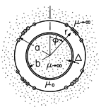
 and conductivity
  , is
wrapped around a circular cylinder having infinite permeability and
radius b. On the other side of an air gap at the radius r = a is a
winding, used to impose the surface current density K = K(t) sin
2
 iz, backed by an infinitely permeable
material in the region a < r.
| (a) | The current density varies so rapidly
that the sheet behaves as an infinite conductor. In this limit,
show that  in the air gap is in the air gap is
 |
| (b) | Now suppose that the driving current is so slowly
varying that the
current induced in the conducting sheet is negligible. Show that
 |
| (c) | Show that if the fields are zero when t < 0 and
there is a step in current, K(t) = Ko u-1(t)
 
|
 . For this
configuration, carry out parts (a), (b), and (c) of Prob. 10.4.5.
Magnetic Diffusion Laws
| (a) | Use (10.5.1)-(10.5.5) to show that for a uniform conductivity   |
| (b) | Now consider J (rather than H) to be z directed but
independent of z, J = Jz (x, y, t) iz, and H (rather than
J) to be transverse, H = Hx (x, y, t) ix + Hy (x, y, t)
iy. Show that
 
|
Magnetic Diffusion Step Response
| (a) | A steady driving current has been established with Ks = Kp = constant. What are the steady H and J in the conducting block? |
| (b) | When t = 0, the driving current is suddenly
turned off. Determine H and J for t > 0.
|
Skin Effect
| (a) | Show that the impedance seen by the current source is |
| (b) | Show that in the limit where b   , Z becomes
the dc resistance a/db , Z becomes
the dc resistance a/db . .
|
| (c) | Show that in the opposite extreme where b   , so
that the current is concentrated near the surface, the
block impedance has resistive and inductive-reactive parts of equal
magnitude and that the resistance is equivalent to that for a slab
having thickness , so
that the current is concentrated near the surface, the
block impedance has resistive and inductive-reactive parts of equal
magnitude and that the resistance is equivalent to that for a slab
having thickness  in the x direction carrying a current that is
uniformly distributed with respect to x. in the x direction carrying a current that is
uniformly distributed with respect to x.
|
| (a) | Determine the sinusoidal steady state response H. |
| (b) | Show that even though the current source is now "showed" by perfectly conducting electrodes, the high-frequency field distribution is still given by (10.7.16), so that in this limit, the current still concentrates at the surface. |
| (c) | Determine the impedance of a length d (in the z direction) of the block. |

