
11.7
Macroscopic Magnetic Forces
In this section, an energy principle is applied to the determination of net forces in MQS systems. With Sec. 11.6 as background, it is appropriate to include the case of multiple terminal pairs. As in Sec. 11.4, the coenergy is again found to be a convenient alternative to the energy.
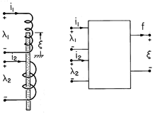
Figure 11.7.1 (a) Magnetoquasistatic system with two electrical terminal pairs and one mechanical degree of freedom. (b) MQS subsystem representing (a). The MQS system is shown schematically in Fig. 11.7.1. It has two electrical terminal pairs and one mechanical degree of freedom. The magnetoquasistatic subsystem now described by an energy principle excludes electrical dissipation and all aspects of the mechanical system, mechanical energy storage and dissipation. The energy principle then states that the input of electrical power through the electrical terminal pairs either goes into a rate of change of the stored magnetic energy or into a rate of change of the work done on the external mechanical world.
As in Sec. 11.6, our starting point in finding the force is a postulated principle of energy conservation. Because the system is presumably MQS, in accordance with (11.3.29), the left-hand side represents the net flux of power into the system. With the addition of the last term and the inherent assumption that there is no electrical dissipation in the subsystem being described, (1) is more than the recasting of Poynting's theorem.
In an MQS system, the voltages are the time rates of change of the flux linkages. With these derivatives substituted into (1) and the expression multiplied by dt, it becomes
This energy principle states that the increments of electrical energy put into the MQS subsystem (as increments of flux d
1 and d
2 through the terminals multiplied by their currents i1 and i2, respectively) either go into the total energy, which is increased by the amount dwm, or into work on the external mechanical system, subject to the force f and experiencing a displacement d
.
With the energy principle written as in (2), the flux linkages are the independent variables. We saw in Example 11.4.2 that it is inconvenient to specify the flux linkages as functions of the currents. With the objective of casting the currents as the independent variables, we now recognize that
and substitute into (2) to obtain
where the coenergy function, seen before in Sec. 11.4, is defined as
We picture the MQS subsystem as having flux linkages
1 and
2, a force f and a total energy wm that are specified once the currents i1 and i2 and the displacement
are stipulated. According to (4), the coenergy is a function of the independent variables i1, i2, and
, wm' = wm' (i1, i2,
), and the change in wm' can also be written as
Because the currents and displacement are independent variables, (4) and (6) can hold only if the coefficients of like terms on the right are equal. Thus,
The last of these three expressions is the key to finding the force f.
Reciprocity Condition
Before we find the coenergy and hence f, consider the implication of the first two expressions in (7) for the electrical terminal relations. Taking the derivative of1 with respect to i2, and of
2 with respect to i1, shows that
Although this reciprocity condition must reflect conservation of energy for any lossless system, magnetically linear or not, consider its implications for a system described by the linear terminal relations.
Application of (8) shows that energy conservation requires the equality of the mutual inductances.
This relation has been derived in Example 11.4.2 from a related but different point of view.
Finding the Coenergy
To find wm', we integrate (4) along a path in the state space (i1, i2,) arranged so that the integral can be carried out without having to know f.
Thus, the first leg of the line integral is carried out on
with the currents equal to zero. Provided that f = 0 in the absence of these currents, this means that the integral of fd
makes no contribution.
The payoff from our formulation in terms of the coenergy rather than the energy comes in being able to carry out the remaining integration using terminal relations in which the flux linkages are expressed in terms of the currents. For the linear terminal relations of (9), this line integration was illustrated in Example 11.4.2, where it was found that
Evaluation of the Force
In general, the inductances in this expression are functions of. Thus, the force f follows from substituting this expression into (7c).
Of course, this expression applies to systems having a single electrical terminal pair as a special case where i2 = 0.
This generalization of the energy method to multiple electrical terminal pair systems suggests how systems with two or more mechanical degrees of freedom are treated.
Example 11.7.1. Driver for a Matrix Printer
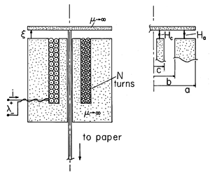
A transducer that is similar to those used to drive an impact printer is shown in Fig. 11.7.2. The device, which is symmetric about the axis, might be one of seven used to drive wires in a high-speed matrix printer. The objective is to transduce a current i that drives the N-turn coil into a longitudinal displacement
of the permeable disk at the top. This disk is attached to one end of a wire, the other end of which is used to impact the ribbon against paper, imprinting a dot.
Figure 11.7.2 Cross-section of axially symmetric transducer similar to the ones used to drive dot matrix printers. The objective here is to determine the force f acting on the plunger at the top. For simplicity, we make a highly idealized model in which the magnetizable material surrounding the coil and filling its core, as well as that of the movable disk, is regarded as perfectly permeable. Moreover, the air gap spacing
is small compared to the radial dimension a, so the magnetic field intensity is approximated as uniform in the air gap. The wire is so fine that the magnetizable material removed to provide clearance for the wire can be disregarded.
With Ha and Hc defined as shown by the inset to Fig. 11.7.2, Ampère's integral law is applied to a contour passing upward through the center of the core, across the air gap at the center, radially outward in the disk, and then downward across the air gap and through the outer part of the stator to encircle the winding in the infinitely permeable material.
A second relation between Ha and Hc follows from requiring that the net flux out of the disk must be zero.
Using this last expression to replace Hc in (14) results in
The magnetic flux linking every turn in the coil is
o Hc
c2. Thus, the total flux linked by the coil is
Finally, the force follows from an evaluation of (13) (specialized to the single terminal pair system of this example).
As might have been expected by one who has observed magnetizable materials pulled into a magnetic field, the force is negative. Given the definition of
in Fig. 11.7.2, the application of a current will tend to close the air gap. To write a dot, the current is applied. To provide for a return of the plunger to its original position when the current is removed, a spring is inserted in the air gap.
In the magnetic transducer of the previous example, the force on the driver disk is due to magnetization. The next example illustrates the force associated with the current density.
Example 11.7.2. Force on a Wire over a Perfectly Conducting Plane
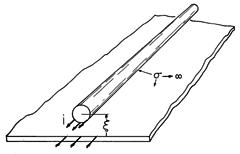
The cross-section of a perfectly conducting wire with its center a distance
above a perfectly conducting ground plane is shown in Fig. 11.7.3. The configuration is familiar from Demonstration 8.6.1. The current carried by the wire is returned in the ground plane. The distribution of this current on the surfaces of the wire and ground plane is consistent with the requirement that there be no flux density normal to the perfectly conducting surfaces. What is the force per unit length f acting on the wire?
Figure 11.7.3 Cross-section of perfectly conducting current-carrying wire over a perfectly conducting ground plane. The inductance per unit length is half of that for a pair of conductors having the center-to-center spacing 2
. Thus, it is half of that given by (8.6.12).
The force per unit length in the
direction then follows from an evaluation of (13) (again adapted to the single terminal pair situation).
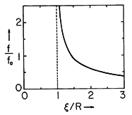
The dependence of this force on the elevation above the ground plane is shown in Fig. 11.7.4. In the limit where the elevation is large compared to the radius of the conductor, (20) becomes
Figure 11.7.4 The force tending to levitate the wire of Fig. 11.7.3 as a function of the distance to the ground plane normalized to the radius R of wire. In Sec. 11.8, we will identify the force density acting on materials carrying a current density J as being J x
o H. Note that the upward force predicted by (20) is indeed consistent with the direction of this force density.
The force on a thin wire, (21), can be derived from this force density by recognizing that the contribution of the self-field of the wire to the total force per unit length is zero. Thus, the force per unit length can be computed using for B the flux density caused by the image current a distance 2
away. The flux density due to this image current has a magnitude that follows from Ampère's integral law as
o i/2
(2
). This field is essentially uniform over the cross-section of the wire, so the integral of the force density J x B over the cross-section of the wire amounts to an integration of the current density J over the cross-section. The latter is the total current i, and so we are led to a force per unit length of magnitude
o i2 /2
(2
), which is in agreement with (21).
The following is a demonstration of the force on current-carrying conductors exemplified previously. It also provides a dramatic demonstration of the existence of induced currents.
Demonstration 11.7.1. Steady State Magnetic Levitation
In the experiment shown in Fig. 11.7.5, the current-carrying wire of the previous example has been wound into a pancake shaped coil that is driven by about 20 amps of 60 Hz current. The conductor beneath is an aluminum sheet of 1.3 cm thickness. Even at 60 Hz, this conductor tends to act as a perfect conductor. This follows from an evaluation of the product of the angular frequency
and the time constant
m estimated in Sec. 10.2. From (10.2.17),
m =
o

a
20, where the average radius is a = 9 cm,
is the sheet thickness and the sheet conductivity is given by Table 7.1.1.
Figure 11.7.5When the pancake coil is driven by an ac current, it floats above the aluminum plate. In this experiment, the coil consists of 250 turns of No. 10 copper wire with an outer radius of 16 cm and an inner one of 2.5 cm. The aluminum sheet has a thickness of 1.3 cm. With a 60 Hz current i of about 20 amp rms, the height above the plate is 2 cm. The time average force, of the type described in Example 11.7.2, is sufficiently large to levitate the coil. As the current is increased, its height above the aluminum sheet increases, as would be expected from the dependence of the force on the height for a single wire, Fig. 11.7.4.
The Torque of Electrical Origin
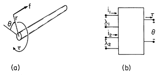
In some of the most important transducers, the mechanical response takes the form of a rotation rather than a translation. The shaft shown in Fig. 11.7.6a might be attached to the rotor of a motor or generator. A force f acting through a lever arm of length r that rotates the shaft through an incremental angle dcauses a displacement d
= rd
. Thus, the incremental work done on the mechanical system fd
becomes
where
is defined as the torque.
Figure 11.7.6 (a) The force f, acting through a lever-arm of length r, produces a torque = rf. (b) Mechanical terminal pair representing a rotational degree of freedom.
If the two terminal pair MQS system of Fig. 11.7.1 had a rotational rather than a displacement degree of freedom, the representation would be the same as has been outlined, except that f

and


. The mechanical terminal pair is now represented as in Fig. 11.7.6b.
The torque follows from (13) as
Among the types of magnetic rotating motors and generators that could be used to exemplify the torque of (23), we now choose a synchronous machine. Although other types of motors are more common, it is a near certainty that if these words are being read with the aid of electrical illumination, the electricity used is being generated by means of a synchronous generator.
Example 11.7.3. A Synchronous Machine
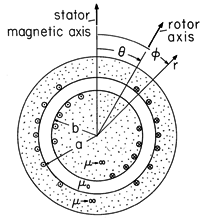
The cross-section of a stator and rotor modeling a rotating machine is shown in Fig. 11.7.7. The rotor consists of a highly permeable circular cylindrical material mounted on a shaft so that it can undergo a rotation measured by the angle
. Surrounding this rotor is a stator, composed of a highly permeable material. In slots, on the inner surface of the stator and on the outer surface of the rotor, respectively, are windings with sinusoidally varying turn densities. These windings, driven by the currents i1 and i2, respectively, give rise to current distributions that might be modeled by surface current densities
Figure 11.7.7 Cross-section of rotating machine.
where Ns and Nr are constants descriptive of the windings. Thus, the current distribution shown on the stator in Fig. 11.7.7 is fixed and gives rise to a magnetic field having the fixed vertical axis shown in the figure. The rotor coil gives rise to a similar field except that its axis is at the angle
of the rotor. The rotor magnetic axis, also shown in Fig. 11.7.7, therefore rotates with the rotor.
Electrical Terminal Relations
With the rotor and stator materials taken as infinitely permeable, the air gap fields are determined by using (24) and (25) to write boundary conditions on the tangential H and then solving Laplace's equation for the air gap magnetic fields (Secs. 9.6 and 9.7). The flux linked by the respective coils is then of the form
where the self-inductances Ls and Lr and peak mutual inductance M are constants.
The dependence of the inductance matrix on the angle of the rotor,
, can be reasoned physically. The rotor is modeled as a smooth circular cylinder, so in the absence of a rotor current i2, there can be no effect of the rotor angle
on the flux linked by the stator winding. Hence, the stator self-inductance is independent of
. Similar reasoning shows that the rotor self-inductance must be independent of rotor angle
. The
dependence of the mutual inductance is plausible because the flux
1 linked by the stator, due to the current in the rotor, must peak when the magnetic axes of the coils are aligned (
= 0) and must be zero when they are perpendicular (
= 90 degrees).
Torque Evaluation
The magnetic torque on the rotor follows directly from using (26) to evaluate (23).
This torque depends on the currents and
in such a way that the magnetic axis of the rotor tends to align with that of the stator. With
= 0, the axes are aligned and there is no torque. If
is slightly positive and the currents are both positive, the torque is negative. This is as would be expected with the magnetic axis of the stator vertical and that of the rotor in the first quadrant (as in Fig. 11.7.7).
Synchronous Operation
In the synchronous mode of operation, the stator current is constrained to be sinusoidal while that on the rotor is a constant. To avoid having to describe the mechanical system, we will assume that the shaft is attached to a mechanical load that makes the angular velocityconstant. Thus, the electrical and mechanical terminals are constrained so that
Under what circumstances can we derive a time average torque on the shaft, and hence a net conversion of energy with each rotation?
With the constraints of (28), the torque follows from (27) as
A trigonometric identity6 makes the implications of this result more apparent.
6(sin (x + y) + sin (x - y))
There is no time average value of either of these sinusoidal functions of time unless one or the other of the frequencies, (
+
) and (
-
), is zero. For example, with the rotation frequency equal to that of the excitation,
the time average torque is
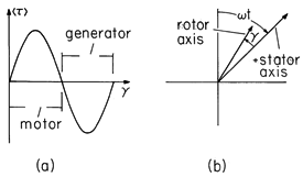
The dependence of the time average torque on the phase angle
is shown in Fig. 11.7.8a. With
between 0 and 180 degrees, there is a positive time average torque acting on the external mechanical system in the direction of rotation
. In this range, the machine acts as a motor to convert energy from electrical to mechanical form. In the range of
from 180 degrees to 360 degrees, energy is converted from mechanical to electrical form and operation is as a generator.
Figure 11.7.8 (a) Time average torque as a function of angle . (b) The rotor magnetic axis lags the clockwise rotating component of the stator magnetic field axis by the angle
.
Stator Field Analyzed into Traveling Waves
From (30), it is clear that a time-average torque results from either a forward (=
) or a backward (
= -
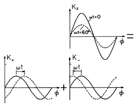
) rotation. This suggests that the field produced by the stator winding is the superposition of fields having magnetic axes rotating in the clockwise and counterclockwise directions. Formally, this can be seen by rewriting the stator surface current density, (24), using the electrical and mechanical constraints of (28). With the use once again of the double-angle trigonometric identity, the distribution of surface current density is separated into two parts.
The sinusoidal excitation produces a standing-wave surface current with nodes at
= 0 and 180 degrees. This is the first distribution in Fig. 11.7.9. Analyzed as it is on the right in (33), and pictured in Fig. 11.7.9, it is the sum of two countertraveling waves. The magnetic axis of the wave traveling to the right is at
=
t.
Figure 11.7.9 With the sinusoidally distributed stator current excited by a current that varies sinusoidally with time, the surface current is a standing wave which can be analyzed into the sum of oppositely propagating traveling waves. We now have the following picture of the synchronous operation found to give rise to the time average torque. The field of the stator is composed of rotating parts, one with a magnetic axis that rotates in a clockwise direction at angular velocity
, and the other rotating in the opposite direction. The frequency condition of (31) therefore represents a synchronous condition in which the "forward" component of the stator field and the magnetic axis of the rotor rotate at the same angular velocity.
In view of the definition of
given in (28), if
is positive, the rotor magnetic axis lags the stator axis by the angle
, as shown in Fig. 11.7.8. When the machine operates as a motor, the forward component of the stator magnetic field "pulls" the rotor along. When the device operates as a generator,
is negative and the rotor magnetic axis leads that of the forward component of the stator field. For generator operation, the rotor magnetic axis "pulls" the forward component of the stator field.
