
11.9
Macroscopic Force Densities
A macroscopic force density F(r ) is the force per unit volume acting on a medium in the neighborhood of r. Fundamentally, the electromagnetic force density is the result of forces acting on those microscopic particles embedded in the material that are charged, or that have electric or magnetic dipole moments. The forces acting on these individual particles are passed along through interparticle forces to the macroscopic material as a whole. In the limit where that volume becomes small, the force density can then be regarded as the sum of the microscopic forces over a volume element
V.
Of course, the linear dimensions of
V are large compared to the microscopic scale.
Strictly, the forces in this sum should be evaluated using the microscopic fields. However, we can gain insight concerning the form taken by the force density by using the macroscopic fields in this evaluation. This is the basis for the following discussions of the force densities associated with unpaired charges and with conduction currents (the Lorentz force density) and with the polarization and magnetization of media (the Kelvin force density).
To be certain that the usage of macroscopic fields in describing the force densities is consistent with that implicit in the constitutive laws already introduced to describe conduction, polarization, and magnetization, the electromagnetic force densities should be derived using energy arguments. These derivations are extensions of those of Secs. 11.6 and 11.7 for forces. We end this section with a discussion of the results of such derivations and of circumstances under which they will predict the same total forces or even material deformations as those derived here.
The Lorentz Force Density
Without restricting the generality of the resulting force density, suppose that the electrical force on a material is due to two species of charged particles. One has N+ particles per unit volume, each with a charge q+, while the other has density N- and a charge equal to -q-. With v denoting the velocity of the macroscopic material and vrepresenting the respective velocities of the carriers relative to that material, the Lorentz force law gives the force on the individual particles.
Note that q- is a positive number.
In typical solids and fluids, the charged particles are either bonded to the material or migrate relative to the material, suffering many collisions with the neutral material during times of interest. In either case, the inertia of the particles is inconsequential, so that on the average, the forces on the individual particles are passed along to the macroscopic material. In either situation, the force density on the material is the sum of (2) and (3), respectively, multiplied by the charged particle densities.
Substitution of (2) and (3) into this expression gives the Lorentz force density
where
u is the unpaired charge density (7.1.6) and J is the current density.
Because the material is in motion, with velocity v, the current density J has not only the contribution familiar from Sec. 7.1 (7.1.4) due to the migration of the carriers relative to the material, but one due to the net charge carried by the moving material as well.
In EQS systems, the first term in (5) usually outweighs the second, while in MQS systems (where the unpaired charge density is negligible), the second term tends to dominate.
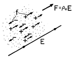
The derivation and Fig. 11.9.1 suggest why the electric term is proportional to the net charge density. In a given region, the force density resulting from the positively charged particles tends to be canceled by that due to the negatively charged particles, and the net force density is therefore proportional to the difference in absolute magnitudes of the charge densities. We exploited this fact in Chap. 7 to let electrically induced material motions evidence the distribution of the unpaired charge density. For example, in Demonstration 7.5.1, the unpaired charge density was restricted to an interface, and as a result, the motion of the fluid was suppressed by constraining the interface. A more recent example is the force on the upper electrode in the capacitor transducer of Example 11.6.1. Here again the force density is confined to a thin region on the surface of the conducting electrode.
Figure 11.9.1 The electric Lorentz force density uE is proportional to the net charge density because the charges individually pass their force to the material in which they are embedded.
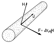
Figure 11.9.2 The magnetic Lorentz force density J x o H.
The magnetic term in (6), pictured in Fig. 11.9.2 as acting on a current-carrying wire, is also familiar. This force density was responsible for throwing the metal disk into the air in the experiment described in Sec. 10.2. The force responsible for the levitation of the pancake coil in Demonstration 11.7.1 was also the net effect of the Lorentz force density, acting either over the volume of the coil conductors or over that of the conducting sheet below. In MQS systems, where the contribution of the "convection" current
uv is negligible, the current density is typically due to conduction. Note that this means that the velocity of the charge carriers is determined by the electric field they experience in the conductor, and not simply by the motion of the conductor. The current density J in a moving conductor is generally not in the direction of motion.9
9Indeed, it is fortunate that the carriers do not have the same velocity as the material, for if they did, it would not be possible to use the magnetic Lorentz force density for electromechanical energy conversion. If we recognize that the rate at which a force f does work on a particle that moves at the velocity v is vf, then it follows from the Lorentz force law, (1.1.1), that the rate of doing work on individual particles through the agent of the magnetic field is v
(v x
o H). The cross-product is perpendicular to v, so this rate of doing work must be zero.
The Kelvin Polarization Force Density
If microscopic particles carrying a net charge were the only contributors to a macroscopic force density, it would not be possible to explain the forces on polarized materials that are free of unpaired charge. Example 11.6.2 and Demonstration 11.6.2 highlighted the polarization force. The experiment was carried out in such a way that the dielectric material did not support unpaired charge, so the force is not explained by the Lorentz force density.
In EQS cases where
u = 0, the macroscopic force density is the result of forces on the microscopic particles with dipole moments. The resulting force density is fundamentally different from that due to unpaired charges; the forces p

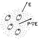
E on the individual microscopic particles are passed along by interparticle forces to the medium as a whole. A comparison of Fig. 11.9.3 with Fig. 11.9.1 emphasizes this point. For a single species of particle, the force density is the force on a single dipole multiplied by the number of dipoles per unit volume Np. By definition, the polarization density P = Np p, so it follows that the force density due to polarization is
This is often called the Kelvin polarization force density.
Figure 11.9.3 The electric Kelvin force density results because the force on the individual dipoles is passed on to the neutral medium.
Example 11.9.1. Force on a Dielectric Material
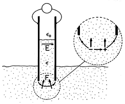
In Fig. 11.9.4, the cross-section of a pair of electrodes that are dipped into a liquid dielectric is shown. The picture might be of a cross-section from the experiment of Demonstration 11.6.2. With the application of a potential difference to the electrodes, the dielectric rises between the electrodes. According to (7), what is the distribution of force density causing this rise?
Figure 11.9.4 In terms of the Kelvin force density, the dielectric liquid is pushed into the field region between capacitor plates because of the forces on individual dipoles in the fringing field. For the liquid dielectric, the polarization constitutive law is taken as linear [(6.4.2) and (6.4.4)]
so that with the understanding that
is a function of position (uniform in the liquid,
o in the gas, and taking a step at the interface), the force density of (7) becomes
By using a vector identity
A
A
= (
x A) x A +

(A
A) and invoking the EQS approximation where
x E = 0, this expression is written as
A second identity
11(

) =


+


converts this expression into one that will now prove useful in picturing the distribution of force density.
Provided that the interface is well removed from the fringing fields at the top and bottom edges of the electrodes, the electric field is uniform not only in the dielectric and gas above and below the interface between the electrodes, but through the interface as well. Thus, throughout the region between the electrodes, there is no gradient of E, and hence, according to (7), no Kelvin force density. The Kelvin force density is therefore confined to the fringing field region where the fluid surrounds the lower edges of the electrodes. In this region,
is uniform, so the force density reduces to the first term in (11). Expressed by this term, the direction and magnitude of the force density is determined by the gradient of the scalar E
E. Thus, where E is varying in the fringing field, it is directed generally upward and into the region of greater field intensity, as suggested by Fig. 11.9.4. The force on the dipole shown by the inset lends further credence to the dipolar origins of the force density.
Although there is no physical basis for doing so, it might seem reasonable to take the force density caused by polarization as being
p E. After all, it is the polarization charge density
p that was used in Chap. 6 to represent the effect of the media on the macroscopic electric field intensity E. The experiment of Demonstration 11.6.2, pictured in Fig. 11.6.7, makes it clear that this force density is not correct. With the interface well removed from the fringing fields, there is no polarization charge density anywhere in the liquid, either at the interface or in the fringing field. If
pE were the correct force density, it would be zero throughout the fluid volume except at the interfaces with the conducting electrodes. There, the forces are perpendicular to the surface of the electrodes. Such a force distribution could not cause the fluid to rise.
The Kelvin Magnetization Force Density
Forces caused by magnetization are probably the most commonly experienced electromagnetic forces. They account for the attraction between a magnet and a piece of iron. In Example 11.7.1, this force density acts on the disk of magnetizable material.
Given that the magnetizable material is made up of microscopic dipoles, each experiencing a force of the nature of (11.8.22), and that the magnetization density M is the number of these per unit volume multiplied by m, it follows from the arguments of the preceding section that the force density due to magnetization is
This is sometimes called the Kelvin magnetization force density.
Example 11.9.2. Force Density in a Magnetized Fluid
With the dielectric liquid replaced by a ferrofluid having a uniform permeability
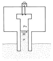
, and the electrodes replaced by the pole faces of an electromagnet, the physical configuration shown in Fig. 11.9.4 becomes the one of Fig. 11.9.5, illustrating the magnetization force density. In such fluids[1], the magnetization results from an essentially permanent suspension of magnetized particles. Each particle comprises a magnetic dipole and passes its force on to the liquid medium in which it is suspended. Provided that the magnetization obeys a linear law, the discussion of the distribution of force density given in Example 11.9.1 applies equally well here.
Figure 11.9.5 In an experiment that is the magnetic analog of that shown in Fig. 11.9.4, a magnetizable liquid is pushed upward into the field region between the pole faces by the forces on magnetic dipoles in the fringing region at the bottom.
Alternative Force Densities
We now return to comments made at the beginning of this section. The fields used to express the Lorentz and Kelvin force densities are macroscopic. To assure consistency between the averages implied by these force densities and those already inherent in the constitutive laws, an energy principle can be used. The approach is a continuum version of that exemplified for lumped parameter systems in Secs. 11.7 and 11.8. In the lumped parameter systems, electrical terminal relations were used to determine a total energy, and energy conservation was used to determine the force. In the continuum system[2], the electrical constitutive law is used to find an energy density, and energy conservation used, in turn, to find a force density. This energy method, like the one exemplified in Secs. 11.7 and 11.8 for lumped parameter systems, describes systems that are loss free. In making practical use of the result, it is assumed that it will be applicable even if there are losses. A more general method, which invokes a principle of virtual power[3], allows for dissipation but requires more empirical information than the polarization or magnetization constitutive law as a starting point.
Force densities derived from more rigorous arguments than given here can have very different distributions from the superposition of the Lorentz and Kelvin force densities. We would expect that the arguments break down when the microscopic particles become so densely packed that the field experienced by one is significantly altered by its nearest neighbor. But surely the difference between the magnetic force density of Lorentz and Kelvin (LK)
we have derived here and the Korteweg-Helmholtz force density (KH) for incompressible media
cited in the literature[2] is not due to interactions between microscopic particles. This latter force density is often obtained for an incompressible material from energy arguments. [Note that with -
and H
H, respectively, playing the roles of dL/d
and i2, the magnetization term in (14) takes a form found for the force on a magnetizable material in Sec. 11.7.]
In Example 11.9.2 (where J = 0), we found the force density of (13) to be confined to the fringing field. By contrast, (14) gives no force density in the fringing region (where
is uniform), but rather puts it all at the interface. According to this latter equation, through the agent of a surface force density (a force density that is a spatial impulse at the interface), the field pulls upward on the interface.
The question may then be asked whether, and how, the two force density expressions can be reconciled. The answer is that if
o M = (
-
o)H, they predict the same motion for any volume-conserving material deformations such as those of an incompressible fluid. We shall demonstrate this for the case of a liquid, such as shown in Fig. 11.9.5, but allowing for the action of a current J as well. As the first step in the derivation, we shall show that (13) and (14) differ by the gradient of a scalar,
(r).
To see this, use a vector identity
A

 A
A = (
x A) x A +

(A
A) to write (13) as
The MQS form of Ampère's law makes it possible to substitute
x H for J in this expression, which then becomes
The second term in this expression is then expanded using a second vector identity
13
 (
(
 ) =
) = 

 +
+ 


This expression differs from (14) by the last term, which indeed takes the form
where
Now consider Newton's force law for an elemental volume of material. Using the Korteweg-Helmholtz force density, (14), it takes the form
where p is the internal fluid pressure and Fm is the sum of all other mechanical contributions to the force density. Alternatively, using (13) written as (17) as the force density, this same law is represented by
For an incompressible material, none of the other laws needed to describe the continuum (such as mass conservation) involve the pressure.
14 For example, for a compressible fluid, the pressure depends on mass density and temperature, so the pressure does appear in the physical laws. Indeed, in the constitutive law relating these values, the pressure has a well-defined value. However, in an incompressible fluid, the constitutive law relating the pressure to mass density and temperature is not relevant to the prediction of material motion. Thus, if (19) is used, p appears only in that equation and if (20) is used, p'p -
appears only in that expression. This means that p and p' play identical roles in predicting the deformation. In an incompressible material, it is the role of the pressure to adjust itself so that only volume conserving deformations are allowed.
15Like the "perfectly permeable material" of magnetic circuits, in which B remains finite as H goes to zero, the "perfectly incompressible" material is one in which the pressure remains finite even as the material becomes infinitely "stiff" to all but those deformations that conserve volume.
The two formulations would differ in what one would call the pressure, but would result in the same material deformation and velocity. An example is the height of rise of the fluid between the parallel plates in Fig. 11.9.5.
Included in the class of incompressible deformations are rigid body motions. If used self-consistently, force densities that differ by the gradient of a "
" will predict the same motions of rigid bodies. Thus, the net force on a body surrounded by free space will be the same whether found using the Lorentz-Kelvin or the Korteweg-Helmholtz force density. The following example illustrates this concept.
Example 11.9.3. Magnetic Force on a Magnetizable Current-Carrying Material
A block of conducting material having permeability
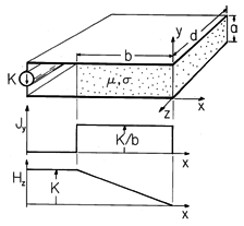
is shown in Fig. 11.9.6 sandwiched between perfectly conducting plates. A current source, distributed over the left edges of these electrodes, drives a constant surface current density K in the +x direction along the left edge of the lower electrode. This current passes through the block in the y direction as a current density
Figure 11.9.6 The block having uniform permeability and conductivity carries a uniform current density in the y direction which produces a z-directed magnetic field intensity. Although the force densities of (13) and (14) have very different distributions in the block, they predict the same net force.
and is returned to the source in the -x direction at the left edge of the upper electrode. The thickness a of the block is small compared to its other two dimensions, so the magnetic field between the electrodes is z directed and dependent only on x. From Ampère's law it follows that
in the conducting block.
The alternative force densities, (13) and (14), have very different distributions in the block. Yet we must find that the net force on the block, found by integrating each over its volume, is the same. To see that this is so, consider first the sum of the Lorentz and Kelvin force densities, (13).
There is no x component of the magnetic field intensity, so for this particular configuration, the magnetization term makes no contribution to (13). Evaluation of the first term using (19) and (20) then gives
Integration of this force density over the volume amounts to a multiplication by the cross-sectional area ad, and integration on x. Thus, the net force predicted by using the force density of Lorentz and Kelvin is
Now, the Korteweg-Helmholtz force density given by (14) is evaluated. The permeability
is uniform throughout the interior of the block, so the magnetization term is again zero there. However,
is a step function at the ends of the block, where x = -b and x = 0. Thus,
is an impulse there and we must take care to include the contributions from the surface regions in our integration. Evaluation of the x component of (14) using (21) and
Integration of (25) over the volume of the block therefore gives
Note that Hz is constant through the interface at x = -b. Thus, the integration of the last term can be carried out. Simplification of this expression gives the same total force as found before, (24).
The distributions of the force densities given by (13) and (14) are generally different, even very different. It is therefore natural to ask which of the two is the "right" one. In general, until the "other" force densities acting on the medium in question are specified, this question cannot be answered. Here, where a discussion of continuum mechanics is beyond our purview, we have identified a class of mechanical deformations (namely, those that are volume conserving or "incompressible"), where these force densities are equally valid. In fact, any other force density differing from these by a term having the form
would also be valid. The combined Lorentz and Kelvin force densities have the advantage of a satisfying physical interpretation. However, the derivation has the weakness of making an ad hoc use of the macroscopic fields. Force densities resulting from an energy argument have the advantage of dealing rigorously with the macroscopic fields.


