
12.4
Antenna Radiation Fields in the Sinusoidal Steady State
Antennae are designed to transmit and receive electromagnetic waves. As we know from Sec. 12.2, the superposition integrals for the scalar and vector potentials result in both the radiation and near fields. If we confine our interest to the fields far from the antenna, extensive simplifications are achieved.
Many types of antennae are composed of driven conducting elements that are extremely thin. This often makes it possible to use simple arguments to approximate the distribution of current over the length of the conductor. With the current distribution specified at the outset, the superposition integrals of Sec. 12.3 can then be used to determine the associated fields.
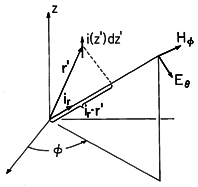
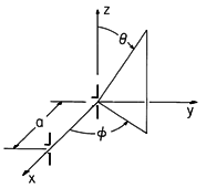
An element idz' of the current distribution of an antenna is pictured in Fig. 12.4.1 at the source location r'. If this element were at the origin of the spherical coordinate system shown, the associated radiation fields would be as given by (12.2.23) and (12.2.24). With the distance to the current element r' much less than r, how do we adapt these expressions so that they represent the fields when the incremental source is located at r' rather than at the origin?
Figure 12.4.1 Incremental current element at r' is source for radiation field at (r, ,
).
The current elements comprising the antenna are typically within a few wavelengths of the origin. By contrast, the distance r (say, from a TV transmitting antenna, where the wavelength is on the order of 1 meter, to a receiver 10 kilometers away) is far larger. For an observer in the neighborhood of a point (r,
,
), there is little change in sin
/r, and hence in the magnitude of the field, caused by a displacement of the current element from the origin to r'. However, the phase of the electromagnetic wave launched by the current element is strongly influenced by changes in the distance from the element to the observer that are of the order of a wavelength. This is seen by writing the argument of the exponential term in terms of the wavelength
, jkr = j2
r/
.
With the help of Fig. 12.4.1, we see that the distance from the source to the observer is r - r'
ir. Thus, for the current element located at r' in the neighborhood of the origin, the radiation fields given by (12.2.23) and (12.2.24) are
Because E and H are vector fields, yet another approximation is implicit in writing these expressions. In shifting the current element, there is a slight shift in the coordinate directions at the observer location. Again, because r is much larger than |r'|, this slight change in the direction of the field can be ignored. Thus, radiation fields due to a superposition of current elements can be found by simply superimposing the fields as though they were parallel vectors.
Distributed Current Distribution
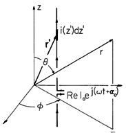
A wire antenna, driven by a given current distribution Re [
(z) exp (j
t)], is shown in Fig. 12.4.2. At the terminals, the complex amplitude of this current is
= Io exp (j
t +
o ). It follows from (1) and the superposition principle that the magnetic radiation field for this antenna is
Figure 12.4.2 Line current distribution as source of radiation field.
Note that the role played by id for the incremental dipole is now played by i(z' )dz'. For convenience, we define a field pattern function
o(
) that gives the
dependence of the E and H fields
where l is the length of the antenna and
o(
) is dimensionless. With the aid of
o(
), one may write (3) in the form
By definition,
(
' ) = Ioexp(j
o ) if z' is evaluated at the terminals of the antenna. Thus,
o is neither a function of Io nor of
o. In order to evaluate (5), one needs to know the current dependence on z' ,
(z' ). One can show that the current distribution on a (open-ended) thin wire is made up of a "standing wave" with the dependence sin (2
s/
) upon the coordinate s measured along the wire, from the end of the wire. The proof of this statement will be presented in Chapter 14, when we shall discuss the current distribution in a coaxial cable.
Example 12.4.1. Radiation Pattern of Center-Fed Wire Antenna
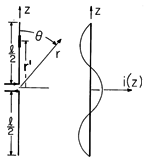
A wire antenna, fed at its midpoint and on the z axis, is shown in Fig. 12.4.3. The current distribution is "given" according to the above remarks.
Figure 12.4.3 Center-fed wire antenna with standing-wave distribution of current. In setting up the radiation field superposition integral, (5), observe that r'
ir = z' cos
.
Evaluation of the integral7 then gives
7To carry out the integration, first express the integration over the positive and negative segments of z' as separate integrals. With the sine functions represented by the sum of complex exponentials, the integration is reduced to a sum of integrations of complex exponentials.
The radiation pattern of the wire antenna is proportional to the absolute value squared of the
-dependent factor of
o
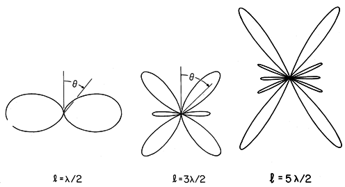
In viewing the plots of this radiation pattern shown in Fig. 12.4.4, remember that it is the same in any plane of constant
. Thus, a three-dimensional picture of the function
(
,
) is generated by rotating one of these patterns about the z axis.
Figure 12.4.4 Radiation patterns for center-fed wire antennas. The radiation pattern for a half-wave antenna differs little from that for the short dipole, shown in Fig. 12.2.7. Because of the interference between waves generated by segments having different phases and amplitudes, the pattern for longer wires is more complex. As the length of the antenna is increased to many wavelengths, the number of lobes increases.
Arrays
Desired radiation patterns are often obtained by combining driven elements into arrays. To illustrate, consider an array of 1 + n elements, the first at the origin and designated by "0". The others are designated by i = 1
n and respectively located at ai. We can find the radiation pattern for the array by summing over the contributions of the separate elements. Each of these takes the form of (5), with r
r - ai
ir , Io
Ii,
o

i, and
o (
)

(
).
In the special case where the magnitude (but not the phase) of each element is the same and the elements are identical, so that Ii = Io and
i =
o, this expression can be written as
where the array factor is
Note that the radiation pattern of the array is represented by the square of the product of
o, representing the pattern for a single element, and the array factor
a. If the n + 1 element array is considered one element in a second array, these same arguments could be repeated to show that the radiation pattern of the array of arrays is represented by the square of the product of
o,
a and the square of the array factor of the second array.
Figure 12.4.5 Array consisting of two elements with spacing, a.
Example 12.4.2. Two-Element Arrays
The elements of an array have a spacing a, as shown in Fig. 12.4.5. The array factor follows from evaluation of (12), where ao = 0 and a1 = aix. The projection of ir into ix gives (see Fig. 12.4.5)
It follows that
It is convenient to write this expression as a product of a part that determines the phase and a part that determines the amplitude.
Dipoles in Broadside Array
With the elements short compared to a wavelength, the individual patterns are those of a dipole. It follows from (4) that
With the dipoles having a half-wavelength spacing and driven in phase,
The magnitude of the array factor follows from (15).
The radiation pattern for the array follows from (16) and (18).
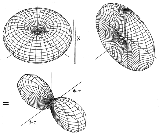
Figure 12.4.6 geometrically portrays how the single-element pattern and array pattern multiply to provide the radiation pattern. With the elements a half-wavelength apart and driven in phase, electromagnetic waves arrive in phase at points along the y axis and reinforce. There is no radiation in the
x directions, because a wave initiated by one element arrives out of phase with the wave being initiated by that second element. As a result, the waves reinforce along the y axis, the "broadside" direction, while they cancel along the x axis.
Figure 12.4.6 Radiation pattern of dipoles in phase, half-wave spaced, is product of pattern for individual elements multiplied by the array factor.
Dipoles in End-Fire Array
With quarter-wave spacing and driven 90 degrees out of phase,
the magnitude of the array factor follows from (15) as
The radiation pattern follows from (16) and (21).
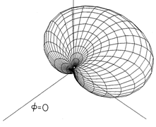
Shown graphically in Fig. 12.4.7, the pattern is now in the -x direction. Waves initiated in the -x direction by the element at x = a arrive in phase with those originating from the second element. Thus, the wave being initiated by that second element in the -x direction is reinforced. By contrast, the wave initiated in the +x direction by the element at x = 0 arrives 180 degrees out of phase with the wave being initiated in the +x direction by the other element. Thus, radiation in the +x direction cancels, and the array is unidirectional.
Figure 12.4.7 Radiation pattern for dipoles quarter-wave spaced, 90 degrees out of phase.
Finite Dipoles in End-Fire Array
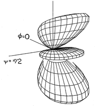
Finally, consider a pair of finite length elements, each having a length l, as in Fig. 12.4.3. The pattern for the individual elements is given by (8). With the elements spaced as in Fig. 12.4.5, with a =/4 and driven 90 degrees out of phase, the magnitude of the array factor is given by (21). Thus, the amplitude of the radiation pattern is
For elements of length l = 3
/2 (kl = 3
), this pattern is pictured in Fig. 12.4.8.
Figure 12.4.8 Radiation pattern for two center-fed wire antennas, quarter-wave spaced, 90 degrees out-of-phase, each having length 3 /2.
Gain
The time average power flux density,
Sr (
,
)
, normalized to the power flux density averaged over the surface of a sphere, is called the gain of an antenna.
If the direction is not specified, it is implied that G is the gain in the direction of maximum gain.
The radial power flux density is the Poynting flux, defined by (11.2.9). Using the time average theorem, (11.5.6), and the fact that the ratio of E to H for the radiation field is
/
, (2), gives
Because the radiation pattern expresses the (
,
) dependence of |E
|2 with a multiplicative factor that is in common to the numerator and denominator of (24), G can be evaluated using the radiation pattern
for
Sr
.
Example 12.4.3. Gain of an Electric Dipole
For the electric dipole, it follows from (1) and (2) that the radiation pattern is proportional to sin2 (
). The gain in the
direction is then
and the "gain" is 3/2.
