12.8
Summary
This chapter has been concerned with the determination of the electrodynamic fields associated with given distributions of current density J (r, t) and charge density
(r, t). We began by extending the vector potential A and scalar potential
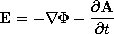
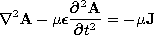
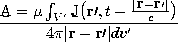
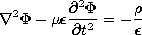
to situations where both the displacement current density and the magnetic induction are important. The resulting field-potential relations, the first two equations in Table 12.8.1, are familiar from quasistatics, except that -
A/
Table 12.8.1 ELECTRODYNAMIC SOURCE POTENTIAL RELATIONS
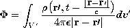
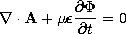
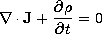
(12.1.1) (12.1.3) (12.1.8) (12.3.2) (12.1.10) (12.3.1) (12.1.7) (12.1.20) Given the sources everywhere, solutions to the inhomogeneous wave equations are given by the respective superposition integrals of Table 12.8.1. As a reminder that the sources in these integrals are related, the charge conservation law, (12.1.20), is included. The relation between J and
The derivation of the superposition integrals began in Sec. 12.2 with the identification of the potentials, and hence fields, associated with dipoles. Here, in remarkably simple terms, it was seen that the effect on the field at r of the source at r' is delayed by the time required for a wave to propagate through the intervening distance at the velocity of light, c. In the quasistatic limit, where times of interest are long compared to this delay time, the electric and magnetic dipoles considered in Sec. 12.2 are those familiar from electroquasistatics (Sec. 4.4) and magnetoquasistatics (Sec. 8.3), respectively. With the complete description of electromagnetic radiation from these dipoles, we could place the introduction to quasistatics of Sec. 3.3 on firmer ground.
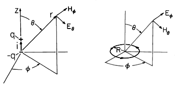
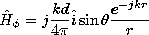
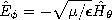
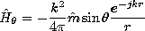
For the purpose of determining the radiation pattern and radiation resistance of antennae, the radiation fields are of primary interest. For the sinusoidal steady state, Section 12.4 illustrated how the radiation fields could be superimposed to describe the radiation from given distributions of current elements representing an antenna, and how the fields from these elements could be combined to represent the radiation from an array. The elementary solutions from which these fields were constructed are those of an electric dipole, as summarized in Table 12.8.2. A similar use can be made of the magnetic dipole radiation fields, which are also summarized for reference in the table.
TABLE 12.8.2 DIPOLE RADIATION FIELDS
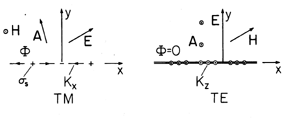
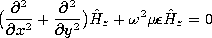
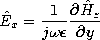
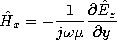
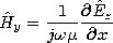
(12.2.23) (12.2.34) (12.2.24) (12.2.35) The fields associated with planar sheet sources, the subject of Sec. 12.6, will be encountered again in the next chapter. In Sec. 12.6, the surface sources were taken as given. We found that sources having distributions that were dependent on (x, t) (independent of z) could be classified in accordance with the fields they produced, as summarized by the figures in Table 12.8.3. The TM and TE sources and fields, respectively, are described in terms of Hz and Ez by the relations given in the table. In the limit
2

kx2, these source and field cases are EQS and MQS, respectively. This condition on the frequency means that the period 2
/
x/c for an electromagnetic wave to propagate a distance equal to a wavelength
Table 12.8.3 TWO-DIMENSIONAL ELECTRODYNAMIC FIELDS
(12.6.9) (12.6.33) (12.6.6) (12.6.29) (12.6.7) (12.6.30) (12.6.13) In the form of uniform and nonuniform plane waves, the Cartesian coordinate solutions to the homogeneous wave equation for these two-dimensional fields are summarized by the last equations in Table 12.8.3. In this chapter, we have thought of kx as being imposed by the given source distribution. As the frequency is raised, with the wavelength along the x direction
y directions (are evanescent in those directions) and are in temporal synchronism with the sources. These are the EQS and MQS limits. As the frequency is raised, the fields extend further and further in the
In the next chapter, these field solutions will be found fundamental to the description of fields in the presence of perfect conductors and dielectrics.