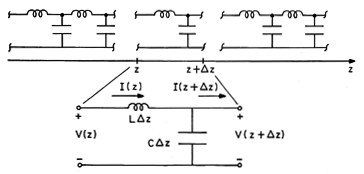
The theme of this section is the distributed parameter
transmission line shown in Fig. 14.1.1. Over any finite axial
length of interest, there is an infinite set of the basic units shown
in the inset, an infinite number of capacitors and
inductors. The parameters L and C are defined per unit length.
Thus, for the segment shown between z +  z and z, L
 z is
the series inductance (in Henrys) of a section of the distributed
line having length
  z, while C
  z is the shunt capacitance (in
Farads).
 Fig 14.1.1 Incremental length of distributed
parameter transmission line.
In the limit where the incremental length  z
z  0,
this distributed parameter transmission line serves as a model
for the propagation of three types of
electromagnetic fields.
First, it gives an exact representation of uniformly polarized
electromagnetic plane waves. Whether these are waves in
free space, perhaps as launched by the dipole considered in Sec. 12.2,
or TEM waves between plane parallel perfectly conducting electrodes,
Sec. 13.1, these fields depend only on one spatial coordinate and time.
Second, we will see in the next section that the
distributed parameter transmission line represents exactly the (z,
t) dependence of TEM waves propagating on pairs of axially uniform
perfect conductors forming transmission lines of arbitrary
cross-section. Such systems are a generalization of the parallel
plate transmission line. By contrast with that special case, however,
the fields generally depend on the transverse coordinates. These
fields are therefore, in general, three dimensional.
Third, it represents in an approximate way, the (z, t)
dependence for systems of large aspect ratio, having lengths over
which the fields evolve in the z direction (e.g., wavelengths)
that are long compared to the transverse dimensions. To reflect the
approximate nature of the model and the two- or three-dimensional
nature of the system it represents, it is sometimes said to be
quasi-one-dimensional.
We can obtain a pair of partial differential equations governing
the transmission line current I(z, t) and voltage V(z, t) by first
requiring that the currents into the node of the elemental section sum
to zero

and then requiring that the series voltage drops around the circuit
also sum to zero.

Then, division by  z and recognition that

results in the transmission line equations.


The remainder of this section is an introduction to some of the
physical situations represented by these laws.
Plane-Waves
In the following sections, we will develop techniques for
describing the space-time evolution of fields on transmission lines.
These are equally applicable to the description of electromagnetic
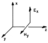
plane waves. For example, suppose the fields take the form shown in
Fig. 14.1.2.

Then, the x and y components of the laws of Ampère and Faraday
reduce to


 Fig 14.1.2 Possible polarization and direction
of propagation of plane wave described by the transmission line
equations.
These laws are identical to the transmission line equations, (4) and
(5), with

With this identification of variables and parameters, the discussion
is equally applicable to plane waves, whether we are considering wave
transients or the sinusoidal steady state in the following sections.
Ideal Transmission Line
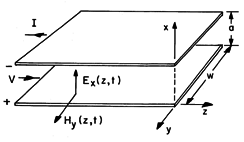
The TEM fields that can exist between the parallel plates of Fig.
14.1.3 can either be regarded as plane waves that happen to meet the
boundary conditions imposed by the electrodes or as a special case of
transmission line fields. The following example illustrates the
transition to the second viewpoint.
 Fig 14.1.3 Example of transmission line where
conductors are parallel plates.
Example 14.1.1. Plane Parallel Plate Transmission Line
In this case, the fields Ex and Hy pictured in Fig.
14.1.2 and described by (7) and (8) can exist unaltered between the
plates of Fig. 14.1.3. If the voltage and current are defined as

Equations (7) and (8) become identical to the transmission line
equations, (4) and (5), with the capacitance and inductance per unit
length defined as

Note that these are indeed the C and L that would be found in
Chaps. 5 and 8 for the pair of perfectly conducting plates shown in
Fig. 14.1.3 if they had unit length in the z direction and were,
respectively, "open circuited" and "short circuited" at the right
end.
As an alternative to a field description, the distributed L-C
transmission line model gives circuit theory interpretation to the
physical processes at work in the actual system. As expressed by (1)
and hence (4), the current I can be a function of z because some of
it can be diverted into charging the "capacitance" of the line.
This is an alternative way of representing the effect of the
displacement current density on the right in Ampère's law, (7).
The voltage V is a function of z because the inductance of the
line causes a voltage drop, even though the conductors are pictured
as having no resistance. This follows from (2) and (5) and embodies
the same information as did Faraday's differential law (8). The
integral of E from one conductor to the other at some location z
can differ from that at another location because of the flux linked by
a contour consisting of these integration paths and closing by
contours along the perfect conductors.
In the next section, we will generalize our picture of TEM waves
and see that (4) and (5) exactly describe transverse waves on
pairs of perfect conductors of arbitrary cross-section. Of course,
L and C are the inductance per unit length and capacitance per unit
length of the particular conductor pair under consideration. The
fields depend not only on the independent variables (z, t) appearing
explicitly in the transmission line equations, but upon the transverse
coordinates as well. Thus, the parallel plate transmission line and
the generalization of that line considered in the next section are
examples for which the distributed parameter model is exact.
In these cases, TEM waves are exact solutions to the boundary value
problem at all frequencies, including frequencies so high that the
wavelength of the TEM wave is comparable to, or smaller than, the
transverse dimensions of the line. As one would expect from the
analysis of Secs. 13.1-13.3, higher-order modes propagating in the
z direction are also valid solutions. These are not
described by the transmission line equations (4) and (5).
Quasi-One-Dimensional Models
The distributed parameter model is also often used to represent
fields that are not quite TEM. As an example where an approximate
model consists of the distributed L-C network, suppose that the region
between the plane parallel plate conductors is filled to the level
x = d < a by a dielectric of one permittivity with the remainder
filled by
a material having a different permittivity. The region between the
conductors is then one of nonuniform permittivity. We would find that
it is not possible to exactly satisfy the boundary conditions on both
the tangential and normal electric fields at the interface between
dielectrics with an electric field that only had components transverse
to z.
 z and z, L
 z is
the series inductance (in Henrys) of a section of the distributed
line having length
  z, while C
  z is the shunt capacitance (in
Farads).

 z
z  0,
this distributed parameter transmission line serves as a model
for the propagation of three types of
electromagnetic fields.


