The transient response of transmission lines or plane waves is of interest for time-domain reflectometry and for radar. In these applications, it is the delay and shape of the response to pulse-like signals that provides the desired information. Even more common is the use of pulses to represent digitally encoded information carried by various types of cables and optical fibers. Again, pulse delays and reflections are often crucial, and an understanding of how these are endemic to common communications systems is one of the points in this and the next section.
The next four sections develop insights into dynamic phenomena described by the one-dimensional wave equation. This and the next section are concerned with transients and focus on initial as well as boundary conditions to create an awareness of the key role played by causality. Then, with the understanding that effects of the turn-on transient have died away, the sinusoidal steady state response is considered in Secs. 14.5-14.6,
The evolution of the transmission line voltage V(z, t), and hence the associated TEM fields, is governed by the one-dimensional wave equation. This follows by combining the transmission line equations, (14.1.4)-(5), to obtain one expression for V.

This equation has a remarkably general pair of solutions

where V+ and V- are arbitrary functions of variables
 and
and  that are defined as particular combinations of
the independent variables z and t.


To see that this general solution in fact satisfies the wave equation, it is only necessary to perform the derivatives and substitute them into the equation. To that end, observe that

where primes indicate the derivative with respect to the argument of the function. Carrying out the same process once more gives the second derivatives required to evaluate the wave equation.

Substitution of these expression for the derivatives in (1) shows that (1) is satisfied. Functions having the form of (2) are indeed solutions to the wave equation.
According to (2), V is a superposition of fields that
propagate, without changing their shape, in the positive and negative
z directions. With  maintained constant, the component V+ is
constant. With
  a constant, the position z increases with
time according to the law

The shape of the second component of (2) remains invariant when
 is held constant, as it is if the z coordinate decreases at
the rate c. The functions V+ (z - ct) and V- (z + ct)
represent forward and backward waves proceeding without change of
shape at the speed c in the +z and -z directions respectively.
We conclude that the voltage can be represented as a superposition of
forward and backward waves, V+ and V-, which, if the space
surrounding the conductors is free space (where
  =
=  o and
o and  =
=
 o), propagate with the velocity c
  3 x 10⁸ m/s of
light.
Because I(z, t) also satisfies the one-dimensional wave equation, it also can be written as the sum of traveling waves.

The relationships between these components of I and those of V are
found by substitution of (2) and (8) into either of the transmission
line equations, (14.1.4)-(14.1.5), which give the same result if it is
remembered that c = 1/ LC. In summary, as fundamental
solutions to the equations representing the ideal transmission line,
we have


where

Here, Zo is defined as the characteristic impedance of the line.

Typically, Zo is the intrinsic impedance 
 /
/ multiplied by a function of the ratio of dimensions describing the
cross-sectional geometry of the line.
Illustration. Characteristic Impedance of Parallel Wires
For example, the parallel wire transmission line of Example 14.2.2 has the characteristic impedance
where for free space,
/

377
.
Response to Initial Conditions
The specification of the distribution of V and I at an initial
time, t = 0, leads to two traveling waves. It is helpful to
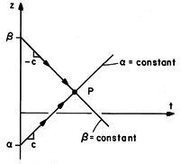
picture the field evolution in the z - t plane shown in Fig.
14.3.1. In this plane, the  = constant and
  = constant
characteristic lines are straight and have slopes
  c,
respectively.

 and z
=
  propagate along the lines of constant
  and
and  to combine at P.
 When t = 0, we are given that along the z axis,


What are these fields at some later time, such as at P in Fig. 14.3.1?
We answer this question in two steps. First, we use the initial conditions to establish the separate components V+ and V- at each position when t = 0. To this end, the initial conditions of (14) and (15) are substituted for the quantities on the left in (9) and (10) to obtain two equations for these unknowns.


These expressions can then be solved for the components in terms of the initial conditions.


The second step combines these components to determine the field
at P in Fig. 14.3.1. Here we use the invariance of V+ along the
line  = constant and the invariance of V- along the line
 = constant. The way in which these components combine at P to
give V and I is summarized by (9) and (10). The total voltage at
P is the sum of the components, while the current is the characteristic
admittance Zo-1 multiplied by the difference of the components.
The following examples illustrate how the initial conditions
determine the invariants (the waves V propagating in the
 z directions) and how these invariants in turn determine the
fields at a subsequent time and different position. They show how the
response at P in Fig. 14.3.1 is determined by the initial conditions
at just two locations, indicated in the figure by the points z =
 and z =
  . Implicit in our understanding of the
dynamics is causality. The response at the location P at some
later time is the result of conditions at (z =
  , t =
0) that propagate with the velocity c in the +z direction and
conditions at (z =
  , t = 0)
that propagate in the -z direction with velocity c.
Example 14.3.1. Initiation of a Pure Traveling Wave
In Example 3.1.1, we were introduced to a uniform plane wave composed of a single component traveling in the +z direction. The particular initial conditions for Ex and Hy [(3.1.9) and (3.1.10)] were selected so that the response would be composed of just the wave propagating in the +z direction. Given that the initial distribution of Ex is
can we now show how to select a distribution of Hy such that there is no part of the response propagating in the -z direction?
In applying the transmission line to plane waves, we make the identification (14.1.9)
We are assured that E- = 0 by making the right-hand side of (19) vanish. Thus, we make
It follows from (18) and (19) that along the characteristic lines passing through (z, 0),
and from (9) and (10) that the subsequent fields are
These are the traveling electromagnetic waves found "the hard way" in Example 3.1.1.
The following example gives further substance to the two-step process
used to deduce the fields at P in Fig. 14.3.1 from those at
(z =  , t = 0) and (z =
  , t = 0). First, the
components V+ and V-, respectively, are deduced at (z =
  ,
t = 0) and (z =
  , t = 0)
from the initial conditions. Because V+ is invariant along the
line
  = constant while V- is invariant along the line
 = constant, we can then combine these components to determine
the fields at P.
Example 14.3.2. Initiation of a Wave Transient
Suppose that when t = 0 there is a uniform voltage Vp between the positions z = -d and z = d, but that outside this range, V = 0. Further, suppose that initially, I = 0 over the entire length of the line.
What are the subsequent distributions of V and I? Once we have found these responses, we will see how such initial conditions might be realized physically.
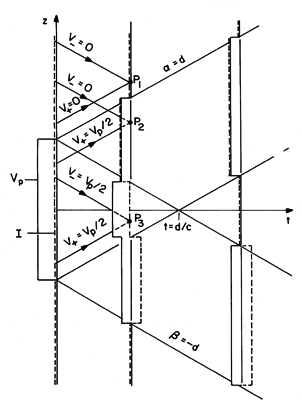
The initial conditions are given a pictorial representation in Fig. 14.3.2, where V(z, 0) = Vi and I(z, 0) = Ii are shown as the solid and broken distributions when t = 0.
Fig 14.3.2 Wave transient pictured in the z - t plane. When t = 0, I = 0 and V assumes a uniform value over the range -d < z < d and is zero outside this range. It follows from (18) and (19) that
Now that the initial conditions have been used to identify the wave components V
, we can use (9) and (10) to establish the subsequent V and I. These are also shown in Fig. 14.3.2 using the axis perpendicular to the z - t plane to represent either V(z, t) (the solid lines) or I(z, t) (the dashed lines). Shown in this figure are the initial and two subsequent field distributions. At point P1, both V+ and V- are zero, so that both V and I are also zero. At points like P2, where the wave propagating from z = d has arrived but that from z = -d has not, V+ is Vp/2 while V- remains zero. At points like P3, neither the wave propagating in the -z direction from z = d or that propagating in the +z direction from z = -d has yet arrived, V+ and V- are given by (27), and the fields remain the same as they were initially.
By the time t = d/c, the wave transient has resolved itself into two pulses propagating in the +z and -z directions with the velocity c. These pulses consist of a voltage and a current that are in a constant ratio equal to the characteristic impedance, Zo.
With the help of the step function u-1(z), defined by
we can carry out these same steps in analytical terms. The initial conditions are
The wave components follow from (18) and (19) and are expressed in terms of the variables
and
because they are invariant along lines where these parameters, respectively, are constant.
The voltage and current at the point P in Fig. 14.3.1 follow from substitution of these expresions into (9) and (10). With
and
expressed in terms of (z, t) using (11), it follows that
These are analytical expressions for the the functions depicted by Fig. 14.3.2.
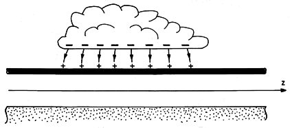
When our lights blink during a thunderstorm, it is possibly due to circuit interruption resulting from a power line transient initiated by a lightning stroke. Even if the discharge does not strike the power line, there can be transients resulting from an accumulation of charge on the line imaging the charge in the cloud above, as shown in Fig. 14.3.3. When the cloud is discharged to ground by the lightning stroke, initial conditions are established that might be modeled by those considered in this example. Just after the lightning discharge, the images for the charge accumulated on the line are on the ground below.


