Transverse electromagnetic (TEM) waves that propagate in the z direction and are polarized in the x direction have electric and magnetic fields

We consider here how waves having this form propagate through a
material with not only uniform permittivity  and permeability
 (as in Secs. 14.1-14.6) but now a uniform conductivity
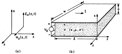
 as well. As suggested by Fig. 14.8.1a, these
fields might constitute plane waves in "infinite" media. They
might also be the fields between the perfectly conducting planar
electrodes of Fig. 14.8.1b. Our first objective in this section is
to see that both the TEM fields in "infinite media" and on the
"strip line" are described exactly by the distributed
parameter model of Sec. 14.7 with R = 0. The ohmic loss introduces
a conductance per unit length G.

 as well as
  and
and  between. With fringing
field ignored, fields in the material have the transverse character
of (a).
 With the introduction of fields having the form of (1) into the laws of Faraday and Ampère, only two of the six equations are not automatically satisfied. These are the x component of Ampère's law with Ohm's law used to express the conduction current

and the y component of Faraday's law

Except for the conduction current, the first term on the right in (2), these are the same equations as featured in Secs. 14.1-14.6. They become the plane parallel transmission-line equations if (2) is multiplied by the plate width w and (3) is multiplied by -a, where a is the plate spacing


where the current I and voltage V are

and

These are the same equations found for the distributed parameter line of Sec. 14.7 with R = 0. Thus, whether representing a plane wave in a uniform lossy material or the transmission-line filled with such a uniform medium, the distributed parameter model is "exact."
From the point of view taken in Sec. 14.2, the geometry of the
parallel conductors in the "strip line" is a special case. In the
problems, the derivation of the transmission line equations given in
Sec. 14.2 is generalized to include the effects of a uniformly
conducting material in the space between the perfect conductors.
Regardless of their cross-sectional geometry, so long as the pair of
conductors are perfectly conducting and the material between them is
uniform, the fields are exactly TEM and exactly represented by the
distributed parameter model. Not only is  (LC) =
  (
(
 )
(8.6.14), but so also is C/G =
  /
/ (7.6.4), regardless
of the cross-sectional geometry.
We now suppose that sinusoidal steady state conditions have been established. Then the voltage and current are represented by (14.7.9) and (14.7.10) with the wave number and characteristic impedance given by (14.7.8) and (14.7.11) with R = 0 and L, C, and G given by (7).


Example 14.8.1. TEM Fields in a Lossy Material between Plane Parallel Plates Terminated in an Open Circuit
With an "open circuit" at z = 0 and driven by a voltage source at z = -l, the parallel plate configuration of Fig. 14.7.1b is equivalent to the open circuit transmission line of Example 14.7.1. With the understanding that
is now given by (8), it follows from (14.7.13) that
Using the values of
+ =
- implied by (14.7.12) in (14.7.10) results in the current distribution
where Zo is evaluated using (9).
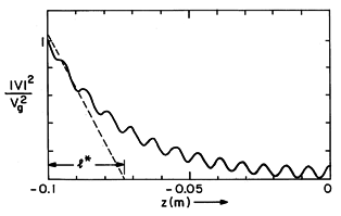
The voltage and current have been specified as a superposition of forward and backward waves, which, respectively, decay in the directions in which their phases propagate. The distribution of the square of the magnitude of V (of Ex) predicted by (10) (and hence of the time average dissipation density or time average electric energy density) is illustrated by Fig. 14.8.2. In this case, the electrical dissipation is small enough so that a standing wave pattern is evident. The wave propagating and decaying to the right interferes with the wave propagating and decaying to the left in such a way that the boundary condition at z = 0 is satisfied. In the neighborhood of z = 0, where the wave traveling to the left has not yet decayed appreciably, the two waves interfere to form the familiar standing wave pattern. However, at the left, the wave traveling to the left has largely decayed and so interferes with the wave traveling to the right to produce no more than a ripple in the total field magnitude. Further insights concerning these field distributions will come from considering some limits of the dispersion equation discussed next.

 as
a function of position z for a slightly damped electromagnetic
wave.
  = 12 x 1010 rad/s, l = 0.1 m,
  =
=  o,
o,
 =
=  o, and
  = 0.1 S/m, so
 /
/ =
= 
 e = 10.6 and l* = 0.0265 m.
 The first and second terms under the radical in the dispersion equation, (8), represent the displacement and conduction current densities, respectively. The relative importance of these current densities is determined by the relationship between the frequency and the reciprocal charge relaxation time. This is evident if (8) is written as

where  e
e 
 /
/ is the charge relaxation time.
Displacement Current Much Greater Than Conduction Current: 
 e
e  1.
1.
In this limit, the waves are essentially electromagnetic, with some
damping due to the finite conductivity. The second term under the
radical in (12) is small compared to the first. Thus, the expression
can be given a convenient approximation by using the first two terms
in a binomial expansion.12
12 With x
 -j/
-j/
 e, (1 +
x)1/2
  (1 +
(1 +  x)
x)

The natural distance over which the electromagnetic wave decays by 1/e is 2l*, where the characteristic length l* is defined in (13) as

Note that this length is the reciprocal of the intrinsic
impedance conductivity product. With  e = C/G, the dependence
of
  on
on  given by (13) approximates the high-frequency
range of Fig. 14.7.2.
In the case of Fig. 14.8.2, 
 /
/ = 10.6, so that the
conditions for this low loss limit are met. Because the attenuation
length for the electric field is 2l*, the attenuation
length for the square of the magnitude of Ex is l*, as
shown in the figure, and the length of the system l is several
times larger than the characteristic length l*.
Conduction Current Much Greater Than Displacement Current: 
 e
e  1
1
In this limit, the effects of displacement current are ignored
altogether so that the first term under the radical is neglected
compared to the second, and the dispersion equation is approximated by

Here, 

 2/
2/

 is the skin depth,
familiar from Sec. 10.7.13 Thus, in this regime,
the decay length is
  while the wavelength is 2
 .
The dependence of
  on
on  given by (15) approximates
 in the low-frequency range of Fig. 14.7.2.
13 As defined by (10.7.2), the product of
 and the magnetic diffusion time based on this
length,

 2, is equal to 2.
Example 14.8.2. Overview of TEM Fields in Open Circuit Transmission Line Filled with Lossy Material
Given the properties and dimensions of a simple system and a characteristic time for the dynamics, what are its dominant electromagnetic features? In this example, with the voltage source driving the system of Fig. 14.8.1b (so that the characteristic time is 1/
), the system could be essentially a:
(1) resistor, in which case Ex would be uniform (Sec. 7.2) (2) lossy capacitor, also with an essentially uniform Ex (Sec. 7.9)
distribution of Ex governed by magnetic diffusion (Sec. 10.7)
(3) distribution of inductors and resistors with the (4) lossy transmission line supporting slightly damped electromagnetic waves
With the objective of having a summary way of picturing these possibilities, we recognize that the field distributions [(10) and (11)] are exponential functions of
l(z/l). Thus,
l encapsulates the field distribution. In terms of dimensionless parameters,
e (representing the frequency) and l/l* (representing the length), we write (12) as
and conclude that the field distributions are governed by two parameters, the length of the system relative to the characteristic length (l/l*) and the frequency relative to the reciprocal charge relaxation time (
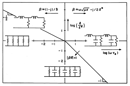
e). The logs of these variables are the coordinates in Fig. 14.8.3. The origin of the plot is at the length equal to the characteristic length, l*, and the angular frequency equal to the reciprocal charge relaxation time, (
/
)-1. These coordinates provide for a systematic overview of the electromagnetic regimes.
Fig 14.8.3 In the length-frequency plane, regimes for TEM fields in material of uniform ,
, and
between perfect conductors having length l (Fig. 14.8.1a). The length is normalized to l* = (
(
/
)-1 and the angular frequency to
e =
/
.
The approximate expressions for the wave number given by (13) and (15), respectively, apply to the right and left of the vertical axis, as indicated at the top of Fig. 14.8.3. It is tempting to jump to the conclusion that there are simply two regimes, the one to the right where the fields are composed of slightly damped electromagnetic waves, and the one to the left involving "skin-effect." However, this is not the whole story, because it does not take into account the length of the system. It is really
l, and not
alone, that determines the field distribution between the plates.
Whether representing a slightly damped electromagnetic wave or magnetic diffusion (skin effect), a small value of
l means that there is little variation of the voltage over the length of the system. In the cases where |
l|
1, the exponentials expressing the z dependence can be approximated by the first terms in a Taylor's series. Thus, in this regime, the voltage (Ex) follows from (10) as being essentially uniform
and the current (Hy) given by (11) takes on an esssentially linear distribution.
The regime in Fig. 14.8.3 where this limit pertains, follows from the dispersion equation, (16).
The line along which
l = 1 can be conveniently pictured by making this expression an equality, solving for l/l* and taking the log.
This makes it clear that for large values of
e, the line of demarcation has a slope of -1, while for small values, its slope is -1/2. This line is shown in Fig. 14.8.3. In the region well to the southwest of this line, the electric field distribution is essentially uniform. The circuits drawn on the respective regions in Fig. 14.8.3 picture the four limiting cases.
In terms of this figure, picture what happens as the frequency is raised for systems that are larger than the matching length, l
l*. In this case, raising the frequency follows a trajectory in the upper half-plane from the left to the right. With the frequency very low, the voltage and current distributions are approximated by (17) and (18). Because
e
1, it follows from the latter equation that the system is essentially a resistor. As the line
l = 1 is approached,
e is still small, so that effects of the displacement current are negligible. That the variation of the fields that comes into play is due to magnetic diffusion is clear from the appropriate limiting expression for
, (15). Indeed, the line
l = 1 in this quadrant approaches the line along which the angular frequency is equal to the reciprocal magnetic diffusion time based on the length l,
as can be seen by rewriting this expression as
In the neighborhood of this line, in the second quadrant where the magnetic diffusion line is shown (the distributed transmission line of Sec. 14.7 with R = 0 and C = 0), the system is magnetoquasistatic (MQS).
As the frequency is raised still further, the displacement current begins to come into effect. The wave number makes a transition from representing the heavily damped waves of magnetic diffusion to the slightly damped electromagnetic waves of the first quadrant.
Consider the contrasting nature of the system with its length much less than the characteristic length, l
l*, as the frequency is raised.
As before, to the far left of the figure, the electric field is uniform and the current is that characteristic of a resistor. This regime, like that just above in the second quadrant, is one of quasi-steady conduction. In this regime, the fields are described by the steady conduction approximation which was the subject of the first half of Chap. 7.
By contrast with the situation in the upper half-plane, the fields now remain uniform until the angular frequency passes well beyond the reciprocal charge relaxation time, the vertical axis. Note that in this range, the voltage and current are those for a distribution of conductances shunting perfectly conducting plates, as shown in Fig. 14.8.3. Thus, all of the conductances and capacitances can be lumped together. Up to this frequency range, the system is electroquasistatic (EQS).
As the frequency is raised still further, effects of magnetic induction come into play and conspire with the displacement current to create field distributions typical of electromagnetic waves. This happens in the range where |
l| = 1, because in this quadrant, the angular frequency is equal to the electromagnetic delay time based on the length of the system,
as can be seen by writing this expression as
In this frequency range and further to the right, the field distributions are those for slightly damped electromagnetic waves.
In summary, far to the left in Fig. 14.8.3, quasi-steady conduction prevails. The dynamic process that first comes into play as the frequency is raised is determined by the length of the system relative to the characteristic length. Systems large enough to be in the upper half-plane are in the MQS regime. Those small enough to be in the lower half-plane are in the EQS regime.
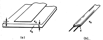
The distributed parameter transmission line is often used to represent the evolution of fields on pairs of conductors surrounded by inhomogeneous dielectrics. Practical examples are shown in Fig. 14.8.4, where the dielectric is piece-wise uniform. In these cases, even if the conductors can be represented as perfectly conducting, so that R = 0, the fields between the conductors are not exactly TEM. Completely transverse waves would propagate with different velocities in the two dielectric regions, and it would not be possible to match boundary conditions at the interfaces. Nevertheless, with C and G, respectively, taken as being the EQS capacitance and conductance per unit length of the open circuit conductors, and L the MQS inductance per unit length of the short circuit conductors, the distributed parameter line of Sec. 14.7 can provide an excellent model.

In cases where the material between the conductors is inhomogeneous, the distributed parameter model provides a good approximation of the principal mode of propagation, provided that the frequency is low enough to insure that the wavelength in the z direction is long compared to the cross-sectional dimensions. For example, it is shown in the problems that there is a z-directed E in the strip line of Fig. 14.8.4a, so the fields are not TEM. However, if one neglects fringing fields one can show that Ez is small compared to the transverse fields if

Thus, the distributed parameter model is exact if the dielectric is
uniform ( a =
a =  b), and approximately correct if
  a = 2
a = 2 a/
a/ is small enough to fulfill the inequality.


