The transmission line model of Sec. 14.7 can also represent the losses in the parallel conductors. With the conductors of finite conductivity, currents in the z direction cause a component of E in that direction. Because the tangential E is continuous at the surfaces of the conductors, this axial electric field extends into the insulating region between the conductors as well. We conclude that the fields are no longer exactly TEM when the conductor losses are finite.
Under what circumstances can the series distributed resistance R
be used to represent the conductor losses? We will find that the
conductivity must be sufficiently low so that the skin depth is large
compared to the conductor thickness. One might expect that this
model applies only to the case of large R. Interestingly, we
find that this "constant resistance" model can remain valid even
under circumstances where line losses are small, in the sense that
the decay of a wave within a distance of the order of a wavelength is
small. This occurs when | L|
L|  R, i.e., the effect of the
distributed inductance is much larger than that of the series
resistance. In the opposite extreme, where the effect of the series
resistance is large compared to that of the inductance, the model
represents EQS charge diffusion. A demonstration is used to exemplify
physical situations modeled by this distributed R-C line. These
include solid state electronic devices and physiological systems.
We conclude this section with a model that is appropriate if the skin depth is much less than the conductor thickness. By restricting the model to the sinusoidal steady state, the series distributed resistance R can be replaced by a "frequency dependent" resistance. This approximate model is typical of those used for representing losses in metallic conductors at radio frequencies and above.
We assume conductors in which the conduction current dominates the displacement current. In the sinusoidal steady state, this is true if

Thus, as the frequency is raised, the distribution of current density in the conductors is at first determined by quasi-stationary conduction (first half of Chap. 7) and then by the magnetic diffusion processes discussed in Secs. 10.3-10.7. That is, with the frequency low enough so that magnetic diffusion is essentially instantaneous, the current density is uniformly distributed over the conductor cross-sections. Intuitively, we should expect that the constant resistance R only represents conductor losses at frequencies sufficiently low so that the distribution of current density in the conductors does not depend on rates of change.
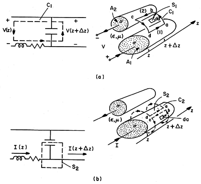
The equations used to describe the incremental circuit in Sec. 14.7 express the integral laws of Faraday and Ampère for incremental lengths of the transmission line. The "current loop equation" for loop C1 in the circuit of Fig. 14.9.1a can be derived by applying Faraday's law to the surface S1 enclosed by the contour C1, also shown in that figure.


 z of
line.
With the line integrals between conductors defined as the voltages and
the flux through the surface as  z LI, this expression becomes

and in the limit where  z
z  0, we obtain

The field equivalent of charge conservation for the
circuit node enclosed by the surface S2 in Fig. 14.9.1b is
Ampère's integral law applied to the surface S2 enclosed by the
contour C2, also shown in that figure. Note that C2 almost
encircles one of the conductors with oppositely directed adjacent
segments completing the z-directed parts of the contour. For a
surface S2 of incremental length  z, Ampère's integral law
requires that

where the contributions from the oppositely directed legs
in the z direction cancel. Ampère's integral law
requires that the integral of H  ds on the contours
essentially surrounding the conductor be the enclosed current I.
Gauss' integral law requires that the surface integral of
 E
E  da be equal to
  z CV. Thus, (5) becomes

and in the limit, the second transmission line equation.

If the current density is uniformly distributed over the cross-sectional areas A1 and A2 of the respective conductors, it follows that the current densities are related to the total current by

In each conductor, Jz =  Ez, so the axial electric fields
required to complete (4) are related to I by

and indeed, the voltage equation is the same as for the distributed line,

where the resistance per unit length has been found to be

Example 14.9.1. Low-Frequency Losses on Parallel Plate Line
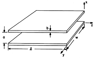
In the parallel plate transmission line shown in Fig. 14.9.2, the conductor thickness is b and the cross-sectional areas are A1 = A2 = bw. It follows from (11) that the resistance is
Fig 14.9.2 Parallel plate transmission line with conductor thickness b that is small compared to skin depth. Under the assumption that the conductor thickness, b, is much less than the plate spacing, a, the inductance per unit length is the same as found in Example 14.1.1, as is also the capacitance per unit length.
14So that the magnetic energy stored in the plates themselves is negligible compared to that between the plates.
As the frequency is raised, the current distribution over the cross-sections of the conductors becomes nonuniform when the skin depth
(10.7.5) gets to be on the order of the plate thickness. Thus, for the model to be valid using the resistance given by (12),
With this inequality we require that the effects of magnetic induction in determining the distribution of current in the conductors be negligible. Under what conditions are we justified in ignoring this effect of magnetic induction but nevertheless keeping that represented by the distributed inductance? Put another way, we ask if the inductive reactance j
L can be large compared to the resistance R and still satisfy the condition of (14).
Combined, these last two conditions require that
We conclude that as long as the conductor thicknesses are small compared to their spacing, R represents the loss over the full frequency range from dc to the frequency at which the current in the conductors ceases to be uniformly distributed. This is true because the time constant
m
L/R =
ab that determines the frequency at which the resistance is equal to the inductive reactance
15 Familiar from Sec. 10.3.
is much larger than the magnetic diffusion time
b2 based on the thickness of the conductors.
Charge Diffusion Transmission Line
If the resistance is large enough so that the inductance has little effect, the lossy transmission line becomes an EQS model. The line is simply composed of the series resistance shunted by the distributed capacitance of Fig. 14.9.3. To see that the voltage (and hence charge) and current on this line are governed by the diffusion equation, (10) is solved for I, with L set equal to zero,

and that expression substituted into the z derivative of (7).


By contrast with the charge relaxation process undergone by charge in a uniform conductor, the charge in this heterogeneous system diffuses. The distributed R-C line is used to model EQS processes that range from those found in neural conduction to relaxation in semiconductors. We can either view the solution of (17) and (18) as a special case from Sec. 14.7 or exploit the complete analogy to the magnetic diffusion processes described in Secs. 10.6 and 10.7.
Demonstration 14.9.1. Charge Diffusion Line
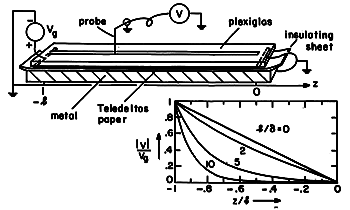
A simple demonstration of the charge diffusion line is shown in Fig. 14.9.4. A thin insulating sheet is sandwiched between a resistive sheet on top (the same Teledeltos paper used in Demonstration 7.6.2) and a metal plate on the bottom.
Fig 14.9.4 Charge diffusion line. With sinusoidal steady state conditions established by means of a voltage source at z = -l and a short circuit at the right, the voltage distribution is the analog of that described for magnetic diffusion in Example 10.7.1. The "skin depth" for the charge diffusion process is given by (10.7.5) with

RC.
With this the new definition of
, the magnitude of the voltage measured by means of the high-impedance voltmeter can be compared to the theory, plotted in Fig. 10.7.2. Typical values are
= 3.5
o, b
= 4.5 x 10⁻⁴ S (where b
is the surface conductivity of the conducting sheet), and a = 25
m, in which case RC =
/(b
)a = 2.7 x 10⁻³ sec/m2 and

0.5 m at a frequency of 500 Hz.
In the previous example, we found that the transmission line model is applicable provided that the conductor thicknesses were small compared to their spacing and to the skin-depth. That the model could be self-consistent from dc up to frequencies at which the inductive impedance dominates resistance is in part attributable to the plane parallel geometry.
To see this, consider a transmission line composed of a circular
cylindrical conductor and a thin sheet, as shown in Fig. 8.6.7. In
Demonstration 8.6.1, it was found that the condition n B = 0 on the conductor surfaces is met at
frequencies for which the skin depth is far greater than the
thickness of the thin sheet conductor. The examples of Sec. 10.4 show
why this is possible. The effective magnetic diffusion time that
determines the frequency at which currents in the conducting sheet
make a transition from a quasi-stationary distribution to one
consistent with n
  B = 0 is

 l, where
 is the thickness of the conductor and l is the distance between
conductors. This is also the L/R time constant governing the
transition from resistance to inductance domination in the distributed
electrodynamic model. We conclude that, even though the current may
be essentially uniform over the conductor cross section, as the
frequency changes from dc to the inductance dominated range, the
current can shift its distribution over the conductor surface. Thus,
in non-planar geometries, the constant R model can be inadequate
even over a frequency range where the skin depth is large compared to
the conductor thickness.
Skin Depth Small Compared to All Dimensions of Interest
In transmission lines used at radio frequencies and higher, it is
usual for the skin depth to be much less than the conductor
thickness, 
 b. In the case of Fig. 14.9.2, 2


 b2. Provided that a > b, it follows from (15)
that the inductive reactance dominates resistance.
Although the line is then very nearly ideal, it is often
long enough so that losses cannot be neglected. We therefore conclude
this section by developing a model, restricted to the sinusoidal
steady state, that accounts for losses when the skin depth is small
compared to all dimensions of interest.
In this case, the axial conduction currents are confined to within a few skin depths of the conductor surfaces. Within a few skin depths, the tangential magnetic field decays from its value at the conductor surface to zero. Because the magnetic field decays so rapidly along a coordinate perpendicular to a given point on the conductor surface, the effects on the magnetic diffusion of spatial variations along the conductor surface are negligible. For this reason, fields in the conductors can be approximated by the one-dimensional magnetic diffusion process described in Sec. 10.7. The following example illustrates this concept.
Example 14.9.2. High-Frequency Losses on Parallel Plate Line
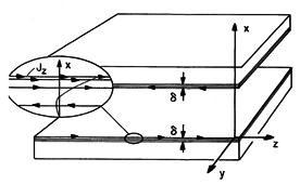
The parallel plate transmission line is shown again in Fig. 14.9.5, this time with the axial current distribution in the conductors in thin regions on the inner surfaces of the conductors rather than uniform. In the conductors, the displacement current is negligible, so that the magnetic field is governed by the magnetic diffusion equation, (10.5.8). In the sinusoidal steady state, the y component of this equation requires that
Fig 14.9.5 Parallel plate transmission line with conductors that are thick compared to the skin depth. The first term on the left is of the order of Hy/(
)2, while the second is of the order of Hy k2 = Hy (2
/
)2 [where
is the wavelength in the axial (z) direction]. Thus, the derivative with respect to z can be ignored compared to that with respect to x, provided that
In this case, (20) becomes the one-dimensional magnetic diffusion equation studied in Sec. 10.7. In the lower conductor, the magnetic field diffuses in the -x direction, so the appropriate solution to (20) is
where Ho is the magnetic field intensity at the surface of the lower conductor [see (10.7.8)]. Ampère's law gives the current density associated with this field distribution
It follows from either integrating this expression over the cross-section of the lower conductor or appealing to Ampère's integral law that the the total current in the lower conductor is
The axial electric field intensity at the surface of the lower conductor can now be written in terms of this total current by first using Ohm's law and the current density of (23) evaluated at the surface and then using (24) to express this field in terms of the total current.
A similar derivation gives an axial electric field at the surface of the upper conductor that is the negative of this result. Thus, we can complete the sinusoidal steady state version of the voltage transmission-line equation, (4).
Because the magnetic energy stored within the conductor is usually negligible compared to that in the region between conductors,
and (26) becomes the first of the two sinusoidal steady state transmission line equations.
The second follows directly from (7).
Comparison of these expressions with those describing the line operating with the conductor thickness much less than the skin depth, (10) and (7), shows that here there is an equivalent distributed resistance.
(Here,
is the permeability of the conductor, not of the region between conductors.) Note that this is the series dc resistance of conductors having width w and thickness
. Because
is inversely proportional to the square root of the frequency, this equivalent resistance increases with the square root of the frequency.


