| | Source and material Configurations
|
|---|
| 15.1.1 |
A theme from Chapter 5 on has been the use of orthogonal modes to
represent field solutions and satisfy boundary conditions. Make a
table identifying examples and problems illustrating this theme.
|
| | Macroscopic Media |
|---|
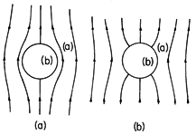
| 15.2.1 | Field lines in the vicinity of a spherical interface between materials
(a) and (b) are shown in Fig. P15.2.1. In each case, describe four
idealized physical situations for which the field lines would be
appropriate.
 Fig P15.2.1
 Fig P15.2.2
|
| 15.2.2 | Dipoles at the center of a spherical region and associated fields are
shown in Fig. P15.2.2. In each case, describe four appropriate
idealized physical situations.
|
| | Approximations
|
|---|
| 15.3.1 | In Fig. 15.3.3, a typical length and time are considered the
independent parameters. Suppose that we wish to see the effect of
varying the conductivity with the size held fixed. For example, with
not only the size but the frequency fixed, the material might be
cooling from a very high temperature where it is molten and an ionic
conductor to a low temperature where it is a good insulator.
Using the conductivity rather than the length for the vertical axis,
select a normalization time for the horizontal axis that is
independent of conductivity, and construct a diagram analogous to Fig.
15.3.3. Identify a "characteristic" conductivity,  *, for
normalizing the conductivity. *, for
normalizing the conductivity.
|
| 15.3.2 | Figure 7.5.3 shows a circular conductor carrying a current that is
returned through a coaxial "perfectly" conducting "can." For
sufficiently low frequencies, the electric field and surface charge
densities are as shown in Fig. 7.5.4. The magnetic field is
described in Example 11.3.1 where the effect of the washer-shaped
conductor is neglected.
| (a) | Sketch E and H, as well as the distribution of
 u and Ju. u and Ju.
|
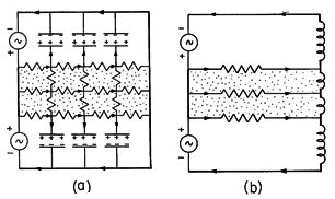
| (b) | Suppose that the length L is on the order of the radius
(a), and (b) is not much smaller than (a). As the frequency is
raised, argue that either charge relaxation will first dominate in
revising the field distribution as in Fig. P15.3.2a, or magnetic
diffusion will dominate as in Fig. P15.3.2b. In the latter case,
describe the current distribution in the conductor by associating it
with an example and a demonstration in this text.
|
| (c) | With L allowed to be large compared to (a), under what
circumstances will the system behave as the lossy transmission line
of Fig. 14.7.1 with G = 0? Discuss the EQS and MQS limits where
this model applies.
|
 Fig P15.3.2
|
| | Energy, Power, and Force |
|---|
| 15.4.1 | For the system considered in Prob. 15.3.2, use the energy approach to
identify the parameters in the low frequency equivalent circuits of
Fig. 15.4.1, and write the ratio of energies in the form of (1).
Ignore the effect of the washer-shaped conductor.
|


 *, for
normalizing the conductivity.
 u and Ju.


