Whether we ignore the magnetic induction and use the EQS
approximation, or neglect the displacement current and make a MQS approximation, times of interest
must be long compared to the time
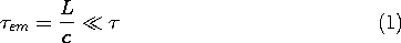
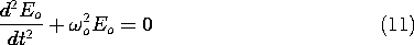
This requirement is given a graphic representation in Fig. 3.4.1.
Figure 3.4.1 Range of characteristic times over which quasistatic approximation is valid. The transit time of an electromagnetic wave is For a given characteristic time (for example, a given reciprocal frequency), it is clear from (1) that the region described by the quasistatic laws is limited in size. Systems can often be divided into subregions that are small enough to be quasistatic but, by virtue of being interconnected through their boundaries, are dynamic in their behavior. With the elements regarded as the subregions, electric circuits are an example. In the physical world of perfect conductors and free space (to which we are presently limited), it is the topology of the conductors that determines whether these subregions are EQS or MQS.
A system that is described by quasistatic laws but retains a dynamical behavior exhibits one or more characteristic times. On the characteristic time axis in Fig. 3.4.1,
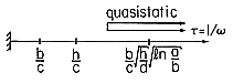
Example 3.4.1. A Quasistatic System Exhibiting Resonance
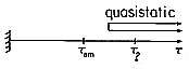
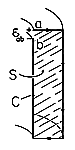
Shown in cross-section in Fig. 3.4.2 is a resonator used in connection with electron beam devices at microwave frequencies. The volume enclosed by its perfectly conducting boundaries can be broken into the two regions shown. The first of these is bounded by a pair of circular plane parallel conductors having spacing d and radius b. This region is EQS and described in Example 3.3.1.
Figure 3.4.2 (a) Quasistatic system showing (b) its EQS subsystem and (c) its MQS subsystem. The second region is bounded by coaxial, perfectly conducting cylinders which form an annular region having outside radius a and an inside radius b that matches up to the outer edge of the lower plate of the EQS system. The coaxial cylinders are shorted by a perfectly conducting plate at the bottom, where z = 0. A similar plate at the top, where z = h, connects the outer cylinder to the outer edge of the upper plate in the EQS subregion.
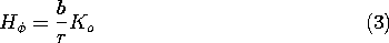
For the moment, the subsystems are isolated from each other by driving the MQS system with a current source Ko (amps/meter) distributed around the periphery of the gap between conductors. This gives rise to axial surface current densities of Ko and -Ko (b/a) on the inner and outer cylindrical conductors and radial surface current densities contributing to J
da in the upper and lower plates, respectively. (Note that these satisfy the MQS current continuity requirement.)
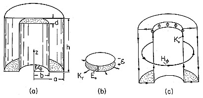
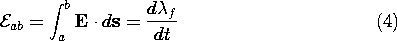
Because of the symmetry, the magnetic field can be determined by using the integral MQS form of Ampère's law. So that there is a contribution to the integration of J
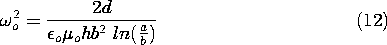
is independent of
Figure 3.4.3 Surface S and contour C for evaluating H-field using Ampère's law.
Thus, in the annulus,
In the regions outside the annulus, H is zero. Note that this is consistent with Ampère's jump condition, (1.4.16), evaluated on any of the boundaries using the already determined surface current densities. Also, we will find in Chap. 10 that there can be no time-varying magnetic flux density normal to a perfectly conducting boundary. The magnetic field given in (3) satisfies this condition as well.
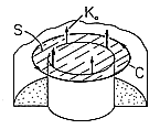
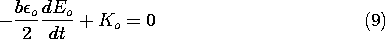
In the hierarchy of MQS laws, we have now satisfied (3.2.5b) and (3.2.6b) and come next to Faraday's law, (3.2.7b). For the present purposes, we are not interested in the details of the distribution of electric field. Rather, we use the integral form of Faraday's law, (1.6.1), integrated on the surface S shown in Fig. 3.4.4. The integral of E
Figure 3.4.4 Surface S and contour C used to determine EMF using Faraday's law.
where the EMF across the gap is as defined by (1.6.2), and the flux linked by C is consistent with (1.6.8).
These last two expressions combine to give
Just as this expression serves to relate the EMF and surface current density at the gap of the MQS system, (3.3.8) relates the gap variables defined in Fig. 3.4.2b for the EQS subsystem. The subsystems are now interconnected by replacing the distributed current source driving the MQS system with the peripheral surface current density of the EQS system.
In addition, the EMF's of the two subsystems are made to match where they join.
With (3.3.8) and (3.3.6), respectively, substituted for Kr and
ab, these expressions become two differential equations in the two variables Eo and Ko describing the complete system.
Elimination of Ko between these expressions gives
where
o is defined as
and it follows that solutions are a linear combination of sin
As might have been suspected from the outset, what we have found is a response to initial conditions that is oscillatory, with a natural frequency
o Eo is the surface charge density on the lower plate in the EQS section. Thus, the oscillation is between the charges in the EQS subsystem and the currents in the MQS subsystem. The distribution of field sources in the system as a whole is determined by a dynamical interaction between the two subsystems.
If the system were driven by a current source having the frequency
Figure 3.4.5 In terms of characteristic time With the region of interest containing media, the appropriate quasistatic limit is often as much determined by the material properties as by the topology. In Chaps. 7 and 10, we will consider lossy materials where the distributions of field sources depend on the time rates of change and a given region can be EQS or MQS depending on the electrical conductivity. We return to the subject of quasistatics in Chaps. 12 and 14.