At least three objectives are set in this section. First, the superposition concept from Sec. 4.3 is exemplified. Second, we begin to deal with fields that are not highly symmetric. The potential proves invaluable in picturing such fields, and so we continue to develop ways of picturing the potential and field distribution. Finally, the potential functions developed will reappear many times in the chapters that follow. Solutions to Poisson's equation as pictured here filling all of space will turn out to be solutions to Laplace's equation in subregions that are devoid of charge. Thus, they will be seen from a second point of view in Chap. 5, where Laplace's equation is featured.
First, consider the potential associated with a point charge at the origin of a spherical coordinate system. The electric field was obtained using the integral form of Gauss' law in Sec. 1.3, (1.3.12). It follows from the definition of the potential, (4.1.4), that the potential of a point charge q is

This "impulse response" for the three-dimensional Poisson's equation is the starting point in derivations and problem solutions and is worth remembering.

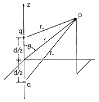
Consider next the field associated with a positive and a negative charge, located on the z axis at d/2 and -d/2, respectively. The configuration is shown in Fig. 4.4.1. In (1), r is the scalar distance between the point of observation and the charge. With P the observation position, these distances are denoted in Fig. 4.4.1 by r+ and r-. It follows from (1) and the superposition principle that the potential distribution for the two charges is

To find the electric field intensity by taking the negative gradient of this function, it is necessary to express r+ and r- in Cartesian coordinates.

Thus, in these coordinates, the potential for the two charges given by (2) is

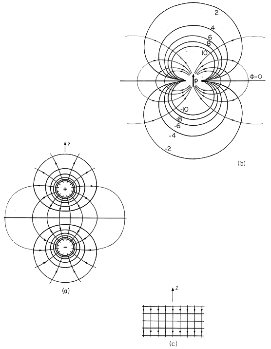
Equation (2) shows that in the immediate vicinity of one or the other of the charges, the respective charge dominates the potential. Thus, close to the point charges the equipotentials are spheres enclosing the charge. Also, this expression makes it clear that the plane z = 0 is one of zero potential.
One straightforward way to plot the equipotentials in detail is to program a calculator to evaluate (4) at a specified coordinate position. To this end, it is convenient to normalize the potential and the coordinates such that (4) is

where

By evaluating  for various coordinate positions, it is possible to
zero in on the coordinates of a given equipotential in an iterative
fashion. The equipotentials shown in Fig. 4.4.2a were plotted in this
way with x = 0. Of course, the equipotentials are actually
three-dimensional surfaces obtained by rotating the curves shown
about the z axis.

Because E is the negative gradient of  , lines of electric field
intensity are perpendicular to the equipotentials. These can
therefore be easily sketched and are shown as lines with arrows in
Fig. 4.4.2a.
Dipole at the Origin
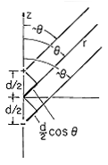
An important limit of (2) corresponds to a view of the field for an observer far from either of the charges. This is a very important limit because charge pairs of opposite sign are the model for polarized atoms or molecules. The dipole is therefore at center stage in Chap. 6, where we deal with polarizable matter. Formally, the dipole limit is taken by recognizing that rays joining the point of observation with the respective charges are essentially parallel to the r coordinate when r d. The approximate
geometry shown in Fig. 4.4.3 motivates the approximations.


Because the first terms in these expressions are very large compared to the second, powers of r+ and r- can be expanded in a binomial expansion.

With n = -1, (2) becomes approximately

Remember, the potential is pictured in spherical coordinates.
Suppose the equipotential is to be sketched that passes through
the z axis at some specified location. What is the shape of the
potential as we move in the positive  direction? On the left in
(8) is a constant. With an increase in
  , the cosine function on the
right decreases. Thus, to stay on the surface, the distance r from
the origin must decrease. As the angle approaches
  /2, the
cosine decreases to zero, making it clear that the equipotential
must approach the origin. The equipotentials and associated lines of
E are shown in Fig. 4.4.2b.
The dipole model is made mathematically exact by defining it as the limit in which two charges of equal magnitude and opposite sign approach to within an infinitesimal distance of each other while increasing in magnitude. Thus, with the dipole moment p defined as

the potential for the dipole, (8), becomes

Another more general way of writing (10) with the dipole positioned at an arbitrary point r' and lying along a general axis is to introduce the dipole moment vector. This vector is defined to be of magnitude p and directed along the axis of the two charges pointing from the - charge to the + charge. With the unit vector ir'r defined as being directed from the point r' (where the dipole is located) to the point of observation at r, it follows from (10) that the generalized potential is

\sectnonumPair of Charges at Infinity Having Equal Magnitude and Opposite Sign Consider next the appearance of the field for an observer located between the charges of Fig. 4.4.2a, in the neighborhood of the origin. We now confine interest to distances from the origin that are small compared to the charge spacing d. Effectively, the charges are at infinity in the +z and -z directions, respectively.

With the help of Fig. 4.4.4 and the three-dimensional Pythagorean theorem, the distances from the charges to the observer point are expressed in spherical coordinates as

In these expressions, d is large compared to r, so they can be expanded by again using (7) and keeping only linear terms in r.

Introduction of these approximations into (2) results in the desired expression for the potential associated with charges that are at infinity on the z axis.

Note that z = r cos  , so what appears to be a complicated
field in spherical coordinates is simply

The z coordinate can just as well be regarded as Cartesian, and the electric field evaluated using the gradient operator in Cartesian coordinates. Thus, the surfaces of constant potential, shown in Fig. 4.4.2c, are horizontal planes. It follows that the electric field intensity is uniform and downward directed. Note that the electric field that follows from (15) is what is obtained by direct evaluation of (1.3.12) as the field of point charges q at a distance d/2 above and below the point of interest.
Other Charge Singularities
A two-dimensional dipole consists of a pair of oppositely charged parallel lines, rather than a pair of point charges. Pictured in a plane perpendicular to the lines, and in polar coordinates, the equipotentials appear similar to those of Fig. 4.4.2b. However, in three dimensions the surfaces are cylinders of circular cross-section and not at all like the closed surfaces of revolution that are the equipotentials for the three-dimensional dipole. Two-dimensional dipole fields are derived in Probs. 4.4.1 and 4.4.2, where the potentials are given for reference.
There is an infinite number of charge singularities. One of the "higher order" singularities is illustrated by the quadrupole fields developed in Probs. 4.4.3 and 4.4.4. We shall see these same potentials again in Chap. 5.

