In solving a boundary value problem, we are in essence finding that distribution of charges external to the region of interest that makes the total field meet the boundary conditions. Commonly, these external charges are actually on the surfaces of conductors bounding or embedded in the region of interest. By way of preparation for the boundary value point of view taken in the next chapter, we consider in this section a direct approach to adjusting surface charges so that the fields meet prescribed boundary conditions on the potential. Analytically, the technique is cumbersome. However, with a computer, it becomes one of a class of powerful numerical techniques[1] for solving boundary value problems.
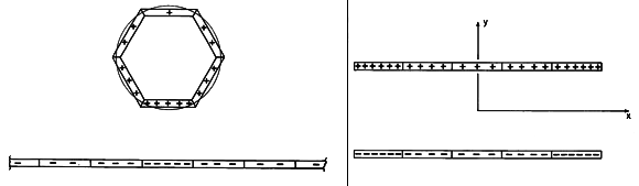
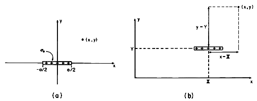
Suppose that the fields are two dimensional, so that the region of interest can be "enclosed" by a surface that can be approximated by strip segments, as illustrated in Fig. 4.8.1a. This example becomes an approximation to the circular conductor over a ground plane (Example 4.7.1) if the magnitudes of the charges on the strips are adjusted to make the surfaces approximate appropriate equipotentials.
Figure 4.8.1 (a) Surface of circular cylinder over a ground plane broken into planar segments, each having a uniform surface charge density. (b) Special case where boundaries are in planes y = constant. With the surface charge density on each of these strips taken as uniform, a "stair-step" approximation to the actual distribution of charge is obtained. By increasing the number of segments, the approximation is refined. For purposes of illustration, we confine ourselves here to boundaries lying in planes of constant y, as shown in Fig. 4.8.1b. Then the potential associated with a single uniformly charged strip is as found in Example 4.5.3.
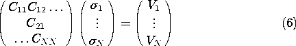
Consider first the potential due to a strip of width (a) lying in the plane y = 0 with its center at x = 0, as shown in Fig. 4.8.2a. This is a special case of the configuration considered in Example 4.5.3. It follows from (4.5.24) with x1 = a/2 and x2 = -a/2 that the potential at the observer location (x, y) is
Figure 4.8.2 (a) Charge strip of Fig. 4.5.8 centered at origin. (b) Charge strip translated so that its center is at (X, Y).
where
With the strip located at (x, y) = (X, Y), as shown in Fig. 4.8.2b, this potential becomes
In turn, by superposition we can write the potential due to N such strips, the one having the uniform surface charge density
i being located at (x, y) = (Xi, Yi).
Given the surface charge densities,
With the strips representing surfaces that are constrained in potential (for example, perfectly conducting boundaries), the charge densities are adjusted to meet boundary conditions. Each strip represents part of an electrode surface. The potential Vj at the center of the j-th strip is set equal to the known voltage of the electrode to which it belongs. Evaluating (4) for the center of the j-th strip one obtains
This statement can be made for each of the strips, so that it holds with j = 1,
N. These relations comprise N equations that are linear in the N unknowns
The potentials V1
Example 4.8.1. Fields of Finite Width Parallel Plate Capacitor
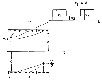
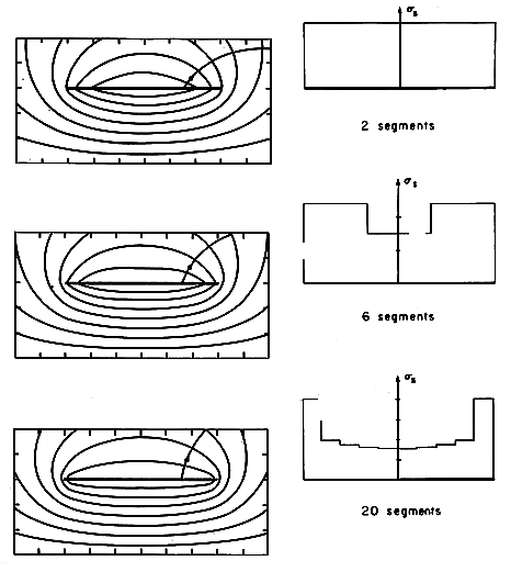
In Fig. 4.8.3, the parallel plates of a capacitor are divided into six segments. The potentials at the centers of those in the top row are required to be V/2, while those in the lower row are -V/2. In this simple case of six segments, symmetry gives
Figure 4.8.3 Charge distribution on plane parallel electrodes approximated by six uniformly charged strips.
and the six equations in six unknowns, (6) with N = 6, reduces to two equations in two unknowns. Thus, it is straightforward to write analytical expressions for the surface charge densities (See Prob. 4.8.1).
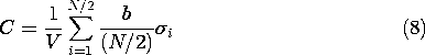
The equipotentials and associated surface charge distributions are shown in Fig. 4.8.4 for increasing numbers of charge sheets. The first is a reminder of the distribution of potential for uniformly charged sheets. Shown next are the equipotentials that result from using the six-segment approximation just evaluated. In the last case, 20 segments have been used and the inversion of (6) carried out by means of a computer.
Figure 4.8.4 Potential distributions using 2, 6, and 20 sheets to approximate the fields of a plane parallel capacitor. Only the fields in the upper half-plane are shown. The distributions of surface charge density on the upper plate are shown to the right. Note that the approximate capacitance per unit length is
This section shows how the superposition integral point of view can be the basis for a numerical approach to solving boundary value problems. But as we proceed to a more direct approach to boundary value problems, it is especially important to profit from the physical insight inherent in the method used in this section.
We have found a mathematical procedure for adjusting the distributions of surface charge so that boundaries are equipotentials. Conducting surfaces surrounded by insulating material tend to become equipotentials by similarly redistributing their surface charge. For example, consider how the surface charge redistributes itself on the parallel plates of Fig. 4.8.4. With the surface charge uniformly distributed, there is a strong electric field tangential to the surface of the plate. In the upper plate, the charges move radially outward in response to this tangential field. Thus, the charge redistributes itself as shown in the subsequent cases. The correct distribution of surface charge density is the one that makes this tangential electric field approach zero, which it is when the surfaces become equipotentials. Thus, the surface charge density is higher near the edges of the plates than it is in the middle. The additional surface charges near the edges result in just that inward-directed electric field which is needed to make the net field perpendicular to the surfaces of the electrodes.
We will find in Sec. 8.6 that the solution to a class of two-dimensional MQS boundary value problems is completely analogous to that for EQS systems of perfect conductors.