Irrotational Field Represented by Scalar Potential: The Gradient Operator and Gradient Integral Theorem
 that are spherical are given by

| (a) | In Cartesian coordinates, what is grad( )? )?
|
| (b) | By the definition of the gradient operator, the unit normal
n to an equipotential surface is

|
 ds
from the origin to (x, y) = (a, a) along the line y = x and show
that it is indeed equal to
  (0, 0) -
  (a, a).


| (a) | Determine E for each potential. |
| (b) | For each function, make a sketch of  and E
using the conventions of Fig. 4.1.3. and E
using the conventions of Fig. 4.1.3.
|
| (c) | For each function, make a sketch using conventions of Fig. 4.1.4. |

 o(t) is a given function of time.
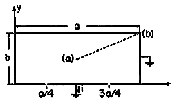
| (a) | Show that the electric field intensity is  |
| (b) | By direct evaluation, show that E is irrotational. |
| (c) | Show that the charge density  is is
 |
| (d) | Show that the tangential E is zero on the boundaries. |
| (e) | Sketch the distributions of  , ,  , and E
using conventions of Figs. 2.7.3 and 4.1.3. , and E
using conventions of Figs. 2.7.3 and 4.1.3.
|
| (f) | Compute the line integral of E  ds
between the center and corner of the rectangular cross-section
(points shown in Fig.~P4.1.4) and show that it is equal to ds
between the center and corner of the rectangular cross-section
(points shown in Fig.~P4.1.4) and show that it is equal to  (a/2, b/2, t). Why would you expect the integration to give the
same result for any path joining the point (a) to any point on the
wall?
|
| (g) | Show that the net charge inside a length d of the
cylinder in the z direction is
  o E o E  da
over the surface enclosing the volume. da
over the surface enclosing the volume.
|
| (h) | Find the surface charge density on the electrode at y =
0 and use your result to show that the net charge on the electrode
segment between x = a/4 and x = 3a/4 having depth d into the
paper is
 |
| (i) | Show that the current, i(t), to this electrode segment
is
 |

 o(t) is a given function of time.
| (a) | Find E. |
| (b) | By evaluating the curl, show that E is indeed irrotational. |
| (c) | Find  . .
|
| (d) | Show that E is tangential to all of the boundaries.
|
| (e) | Using the conventions of Figs. 2.7.3 and 4.1.3, sketch
 , ,  , and E. , and E.
|
| (f) | Use E as found in part (a) to compute the integral of
E  ds from (a) to (b) in Fig.~P4.1.4. Check your
answer by evaluating the potential difference between these points. ds from (a) to (b) in Fig.~P4.1.4. Check your
answer by evaluating the potential difference between these points.
|
| (g) | Evaluate the net charge in the volume by first using Gauss'
integral law and integrating  o E o E  da over the
surface enclosing the volume and then by integrating da over the
surface enclosing the volume and then by integrating  over the
volume. over the
volume.
|

 are given constants.
| (a) | Find E. |
| (b) | By direct evaluation, show that E is indeed irrotational.
|
| (c) | Determine the charge density  . .
|
| (d) | Can you adjust m so that  = 0 throughout the volume? = 0 throughout the volume?
|

 in the z
direction. It consists of a cylinder having a
square cross-section with sides which are resistive sheets
(essentially many resistors in series). Thus, the voltage sources
 V at the corners of the cylinder produce linear distributions of
potential along the sides. For example, the potential between the
corners at (a, 0) and (0, a) drops linearly from V to -V.
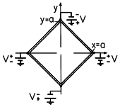
| (a) | Show that the potential inside the cylinder can match that on the walls of the cylinder if it takes the form A(x2 - y2. What is A? |
| (b) | Determine E and show that there is no volume charge
density  within the cylinder. within the cylinder.
|
| (c) | Sketch the equipotential surfaces and lines of electric field intensity. |
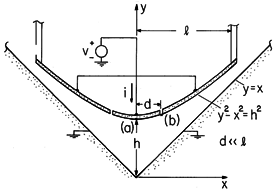
| (a) | Given that the electric field intensity between the groove and tool takes the form
  ds
between point (a) and the
origin. ds
between point (a) and the
origin.
|
| (b) | Find the potential function consistent with (a) and evaluate C by inspection. Check with part (a). |
| (c) | Using the conventions of Figs. 2.7.3 and 4.1.3, sketch lines of constant potential and electric field E for the region between the groove and the tool surfaces. |
| (d) | Determine the total charge on the insulated segment, given v(t). (Hint: Use the integral form of Gauss' law with a convenient surface S enclosing the electrode.) |

Poisson's Equation
 is given by (a). Use
Poisson's equation to show that the associated charge density is as
given by (c) of that problem.
 is given by (a). Use Poisson's
equation to find the charge density.
Superposition Principle
 va(t) and Ib(t)
 vb(t), then Ia(t) + Ib(t)
  va(t) +
vb(t).
Fields Associated with Charge Singularities
 l at x = d/2, y = 0 and
-
 l at x = -d/2, y = 0, as shown in Fig.~P4.4.1. Thus,
the potential distribution is independent of z.
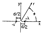
| (a) | Start with the electric field of a line charge, (1.3.13), and determine  . .
|
| (b) | Define the two-dimensional dipole moment as p =
d =
d l and show that in the limit where d l and show that in the limit where d  0 (while
this moment remains constant), the electric potential is 0 (while
this moment remains constant), the electric potential is
 |

 r, this potential
takes the form A cos 2
 /rn. What are the constants A and
n?
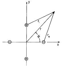
 r).
r).
| (a) | Show that the potential in the neighborhood of the origin takes the form A(x2 - y2). |
| (b) | How would you position the line charges so that in the limit where they moved to infinity, the potential would take the form of (4.1.18)? |
Solution of Poisoon's Equation for Specified Charge Distributions
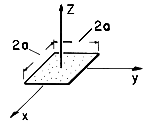
| (a) | Assume that the patch is very thin in the z direction
compared to other dimensions of interest. Over its surface there is
a given surface charge density  s (x, y). Express the
potential s (x, y). Express the
potential  along the z axis for z > 0 in terms of a
two-dimensional integral. along the z axis for z > 0 in terms of a
two-dimensional integral.
|
| (b) | For the particular surface charge distribution  s = s =
 o |xy|/a2 where o |xy|/a2 where  o and a are constants, determine o and a are constants, determine
 along the positive z axis. along the positive z axis.
|
| (c) | What is  at the origin? at the origin?
|
| (d) | Show that  has a z dependence for z has a z dependence for z  a that
is the same as for a point charge at the origin. In
this limit, what is the equivalent point charge for the patch? a that
is the same as for a point charge at the origin. In
this limit, what is the equivalent point charge for the patch?
|
| (e) | What is E along the positive z axis? |
 s =
s =  o
cos
o
cos  , where
  o is a given constant.
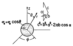

 )1/2.]
| (b) | Show that the potential distribution for the range z < R
along the z axis inside the shell is
 |
| (c) | Show that along the z axis, E is
 |
| (d) | By comparing the z dependence of the potential to that of a
dipole polarized in the z direction, show that the equivalent dipole
moment is qd = (4 /3) /3) o R3. o R3.
|
 o (coulomb/m2), where
  o is a positive constant,
while over the lower half it is -
 o.
o.
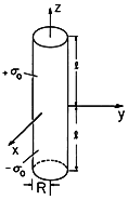
| (a) | Find the potential distribution along the z axis. |
| (b) | Determine E along the z axis. |
| (c) | In the limit where z  l, show that l, show that  becomes
that of a dipole at the origin. What is the equivalent dipole
moment? becomes
that of a dipole at the origin. What is the equivalent dipole
moment?
|
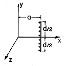
 l and length d is
distributed parallel to the
y axis and centered at the point (x, y, z) = (a, 0, 0), as shown
in Fig.~P4.5.4. Use the superposition integral to show that the
potential
  (x, y, z) is

 l =
l = 
 o
x/l coulomb/m along the lines z =
  a, y = 0, respectively,
between the
points x = 0 and x = l, as shown in Fig.~P4.5.5. Take
  o
as a given charge per unit length and note that
  l varies from
zero to
  o over the lengths of the line charge distributions.
Determine the distribution of
  along the z axis in the range 0
< z < a.

 l (z) is given by

 and E at a position z > a on the z axis.

 in the z direction. On this strip the surface
charge density is


 to z = -
 are each of width 2d with their left and right
edges, respectively, located on the z axis. The one between the z axis
and (x, y) = (2d, 0) has a uniform surface charge density
  o,
while the one between (x, y) = (-2d, 0) and the z axis has
 s = -
s = - o. (Note that the symmetry makes the plane x =
0 one of zero potential.) What must be the value of
  o if
the potential at the center of the right strip, where (x, y) = (d,
0), is to be V?
 l) is distributed is denoted by the vector a,
as shown in the figure.
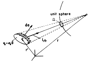
 denoting the position along the line
charge is as shown in Fig.~P4.5.9b. The origin of this coordinate is
at the position on the line segment collinear with a that is
nearest to the observer position r.
| (a) | Argue that in terms of  , the base and tip of the
a vector are as designated in Fig.~P4.5.9b along the , the base and tip of the
a vector are as designated in Fig.~P4.5.9b along the  axis. axis.
|
| (b) | Show that the superposition integral for the potential due
to the segment of line charge at r' is
  |
| (c) | Finally, show that the potential is
 |
| (d) | A straight segment of line charge has the uniform density
 o between the points (x, y, z) = (0, 0, d) and (x, y, z)
= (d, d, d). Using (c), show that the potential o between the points (x, y, z) = (0, 0, d) and (x, y, z)
= (d, d, d). Using (c), show that the potential  (x, y, z) is (x, y, z) is
 |
 (r ), the potential
  follows from (3). This expression has the disadvantage that to find
E, derivatives of
  must be taken. Thus, it is not enough to
know
  at one location if E is to be determined. Start with
(3) and show that a superposition integral for the electric field
intensity is

 is taken to obtain E, the
derivatives are with respect to the observer coordinates with the
source coordinates held fixed.) A similar derivation is given in Sec.
8.2, where an expression for the magnetic field intensity H is
obtained from a superposition integral for the vector potential A.

| (a) | Show that the expression to be satisfied by  is then
not Poisson's equation but rather is then
not Poisson's equation but rather
  . .
|
| (b) | The first step in the derivation of the superposition
integral is to find the response to a point source at the origin,
defined such that

  0, a solution is 0, a solution is
   o. o.
|
| (c) | What is the superposition integral for  ? ?
|
| (a) | With n defined as the unit normal to the interface,
argue that this internal electric field is
 |
| (b) | In deriving the continuity condition on E, (1.6.12),
using (4.1.1), it was assumed that E was finite everywhere, even
within the interface. With a dipole layer, this assumption cannot be
made. For example, suppose that a nonuniform dipole layer  s(x)
is in the plane y = 0. Show that there is a jump in tangential
electric field, Ex, given by s(x)
is in the plane y = 0. Show that there is a jump in tangential
electric field, Ex, given by
 |
Electroquasistatics in the Presence of Perfect Conductors

 o where z = c to
  o (a -
b)/(a - c) where z = b.
The only other charges in the system are at infinity,
where the potential is defined as being zero.
An equipotential surface for this charge distribution passes through the point z = a on the z axis. [This is the same "a" as appears in (a).] If this equipotential surface is replaced by a perfectly conducting electrode, show that the capacitance of the electrode relative to infinity is

 ,
,  )
are defined in the figure.
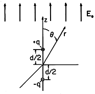
| (a) | The potential, radial coordinate and charge are
normalized such that
  can be
written as can be
written as
 |
| (b) | There is an equipotential surface  = 0 that encloses
these two
charges. Thus, if a "perfectly conducting" object having a surface
taking the shape of this = 0 that encloses
these two
charges. Thus, if a "perfectly conducting" object having a surface
taking the shape of this  = 0 surface is placed in the initially
uniform electric field, the result of part (a) is a solution to the
boundary value problem representing the potential, and hence electric
field, around the object. The following establishes the shape of the
object. Use (b) to find an implicit expression for the radius r
at which the surface intersects the z axis. Use a graphical solution
to show that there will always be such an intersection with r > d/2.
For q = 2, find this radius to two-place accuracy. = 0 surface is placed in the initially
uniform electric field, the result of part (a) is a solution to the
boundary value problem representing the potential, and hence electric
field, around the object. The following establishes the shape of the
object. Use (b) to find an implicit expression for the radius r
at which the surface intersects the z axis. Use a graphical solution
to show that there will always be such an intersection with r > d/2.
For q = 2, find this radius to two-place accuracy.
|
| (c) | Make a plot of the surface  = 0 in a = 0 in a  =
constant
plane. One way to do this is to use a programmable calculator to
evaluate =
constant
plane. One way to do this is to use a programmable calculator to
evaluate  given r and given r and  . It is then
straightforward to pick a . It is then
straightforward to pick a  and iterate on r to find the
location of the surface of zero potential. Make q = 2. and iterate on r to find the
location of the surface of zero potential. Make q = 2.
|
| (d) | We expect E to be largest at the poles of the object. Thus, it is in these regions that we expect electrical breakdown to first occur. In terms of Eo and with q = 2, what is the electric field at the north pole of the object? |
| (e) | In terms of Eo and d, what is the total charge on the northern half of the object. [Hint: A numerical calculation is not required.] |

 Q on the two spheres, as follows:
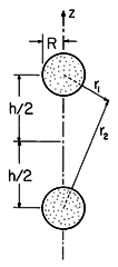
| (a) | First we place the charges at the centers of the spheres.
If R  h, the two
equipotentials surrounding the charges at r1 h, the two
equipotentials surrounding the charges at r1  R and r2 R and r2
 R are almost spherical. If we assume that they are
spherical, what is the potential difference between the two spherical
conductors? Where does the maximum field occur and how big is it? R are almost spherical. If we assume that they are
spherical, what is the potential difference between the two spherical
conductors? Where does the maximum field occur and how big is it?
|
| (b) | We can obtain a better solution by noting that a spherical
equipotential coincident with the top sphere is produced by a set of
three charges. These are the charge -Q at z = -h/2 and the two
charges inside the top sphere properly positioned according to (33)
of appropriate magnitude and total charge +Q. Next, we replace
the charge -Q by two charges, just like we did for the charge +Q.
The net field is now due to four charges. Find the potential
difference and capacitance for the new field configuration and
compare with the previous result. Do you notice that you have
obtained higher-order terms in R/h? You are in the process of
obtaining a rapidly convergent series in powers of R/h.
|
 x.
However, the y - z plane is now a perfectly conducting surface,
so that the electric field is normal to the plane x = 0.
| (a) | Determine the potential in the half-space 0  x. x.
|
| (b) | For the potential found in part (a), what is the equation for the equipotential surface passing through the point (x, y, z) = (a/2, 0, 0)? |
| (c) | For the remainder of this problem, assume that d = 4a. Make a
sketch of this equipotential surface as it intersects the plane z =
0. In doing this, it is convenient to normalize x and y to a
by defining  = x/a and = x/a and  = y/a. A good way to make the plot is then to compute the
potential using a programmable calculator. By iteration, you can
quickly zero in on points of the desired potential. It is sufficient
to show that in addition to the point of part (a), your curve passes
through three well-defined points that suggest its being a closed
surface.
|
| (d) | Suppose that this closed surface having potential V is actually a metallic (perfect) conductor. Sketch the lines of electric field intensity in the region between the electrode and the ground plane. |
| (e) | The capacitance of the electrode relative to the ground plane is defined as C = q/V, where q is the total charge on the surface of the electrode having potential V. For the electrode of part (c), what is C? |
Method of Images
| (a) | Show that  above the plane is above the plane is
 |
| (b) | Show that the equation for the equipotential surface  = V passing through the point z = a < d is
 |
| (c) | Use intuitive arguments to show that this surface encloses
the point charge. In terms of a, d, and  o, show that the
capacitance relative to the ground plane of an electrode having the
shape of this surface is o, show that the
capacitance relative to the ground plane of an electrode having the
shape of this surface is
 |
| (a) | Give the location and sign of the image line charges. |
| (b) | Sketch the equipotentials and E lines in the x - y
plane.
|
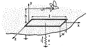
| (a) | Why? |
| (b) | For the purpose of measuring this net charge Q carried by the bird, we have the apparatus pictured in Fig.~P4.7.3. Flush with the ground, a strip electrode having width w and length l is mounted so that it is insulated from ground. The resistance, R, connecting the electrode to ground is small enough so that the potential of the electrode (like that of the surrounding ground) can be approximated as zero. The bird flies in the x direction at a height h above the ground with a velocity U. Thus, its position is taken as y = h and x = Ut. |
| (c) | Given that the bird has flown at an altitude sufficient to make it appear as a point charge, what is the potential distribution? |
| (d) | Determine the surface charge density on the ground plane at y = 0. |
| (e) | At a given instant, what is the net charge, q, on the electrode? (Assume that the width w is small compared to h so that in an integration over the electrode surface, the integration in the z direction is simply a multiplication by w.) |
| (f) | Sketch the time dependence of the electrode charge. |
| (g) | The current through the resistor is dq/dt. Find an expression for the voltage, v, that would be measured across the resistance, R, and sketch its time dependence. |
 l and -
 l run
parallel to the z axis at x = a, y = 0 and x = b, y = 0,
respectively. There are no other charges in the half-space 0 < x.
The y - z plane where x = 0 is composed of finely segmented
electrodes. By connecting a voltage source to each segment, the
potential in the x = 0 plane can be made whatever we want. Show
that the potential distribution you would impose on these electrodes
to insure that there is no normal component of E in the x = 0
plane, Ex (0, y, z), is

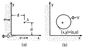
 z directions. The charge per unit length in the z
direction is the constant
  . Metal electrodes extend to infinity
in the x = 0 and y = 0 planes. These electrodes are grounded so that the
potential in these planes is zero.
| (a) | Determine the electric potential in the region x > 0, y > 0. |
| (b) | An equipotential surface passes through the line x = a, y
= a (a < d). This surface is replaced by a metal electrode having
the same shape. In terms of the given constants a, d, and  o,
what is the capacitance per unit length in the z direction of this
electrode relative to the ground planes? o,
what is the capacitance per unit length in the z direction of this
electrode relative to the ground planes?
|
| (a) | Show that for 0 < z, the electric potential along the z
axis is given by
 |
| (b) | Show that the capacitance relative to the ground plane of an
electrode having the shape of the equipotential surface passing
through the point z = d < s on the z axis and enclosing the disk
of charge is
 |
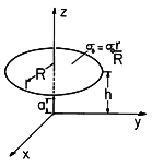
 s =
s =  o r/R. A perfectly conducting electrode has the
shape of an equipotential surface that passes through the point z = a
< h on the z axis and encloses the disk. What is the capacitance of this
electrode relative to the plane z = 0?
 o
between the points (x, y, z) = (0, 0, d) and (x, y, z) = (d, d,
d). There is a perfectly conducting material in the plane z = 0.
Determine the potential for z
  0. [See part (d) of Prob.
4.5.9.]

