Each of the solutions obtained in the preceding section by
separation of variables could be produced by an appropriate potential
applied to pairs of parallel surfaces in the planes x = constant and
y = constant. Consider, for example, the fourth solution in the column
k2  0 of Table 5.4.1, which with a constant multiplier is

 = 0 at y = 0 and at x = 0 and x = a.
This solution has  = 0 in the plane y = 0 and in the planes x
= n
 /k, where n is an integer. Suppose that we set k = n
 /a so that
  = 0 in the plane y = a as well. Then at y =
b, the potential of (1)

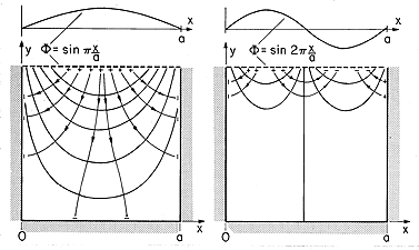
has a sinusoidal dependence on x. If a potential of the form of (2) were applied along the surface at y = b, and the surfaces at x = 0, x = a, and y = 0 were held at zero potential (by, say, planar conductors held at zero potential), then the potential, (1), would exist within the space 0 < x < a, 0 < y < b. Segmented electrodes having each segment constrained to the appropriate potential could be used to approximate the distribution at y = b. The potential and field plots for n = 1 and n = 2 are given in Fig. 5.5.1. Note that the theorem of Sec. 5.2 insures that the specified potential is unique.
But what can be done to describe the field if the wall potentials are not constrained to fit neatly the solution obtained by separation of variables? For example, suppose that the fields are desired in the same region of rectangular cross-section, but with an electrode at y = b constrained to have a potential v that is independent of x. The configuration is now as shown in Fig. 5.5.2.
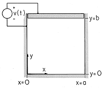
A line of attack is suggested by the infinite number of solutions, having the form of (1), that meet the boundary condition on three of the four walls. The superposition principle makes it clear that any linear combination of these is also a solution, so if we let An be arbitrary coefficients, a more general solution is

Note that k has been assigned values such that the sine function is zero in the planes x = 0 and x = a. Now how can we adjust the coefficients so that the boundary condition at the driven electrode, at y = b, is met? One approach that we will not have to use is suggested by the numerical method described in Sec. 4.8. The electrode could be divided into N segments and (3) evaluated at the center point of each of the segments. If the infinite series were truncated at N terms, the result would be N equations that were linear in the N unknowns An. This system of equations could be inverted to determine the An's. Substitution of these into (3) would then comprise a solution to the boundary value problem. Unfortunately, to achieve reasonable accuracy, large values of N would be required and a computer would be needed.
The power of the approach of variable separation is that it results in solutions that are orthogonal in a sense that makes it possible to determine explicitly the coefficients An. The evaluation of the coefficients is remarkably simple. First, (3) is evaluated on the surface of the electrode where the potential is known.

On
the right is the infinite series of sinusoidal functions with
coefficients that are to be determined. On the left is a given
function of x. We multiply both sides of the expression by sin
(m x/a), where m is one integer, and then both sides of the
expression are integrated over the width of the system.

The functions sin (n x/a) and sin (m
 x/a) are orthogonal
in the sense that the integral of their product over the specified
interval is zero, unless m = n.

Thus, all the terms on the right in (5) vanish, except the one having n = m. Of course, m can be any integer, so we can solve (5) for the m-th amplitude and then replace m by n.

Given any distribution of potential on the surface y = b, this integral can be carried out and hence the coefficients determined. In this specific problem, the potential is v at each point on the electrode surface. Thus, (7) is evaluated to give

Finally, substitution of these coefficients into (3) gives the desired potential.

Each product term in this infinite series satisfies Laplace's equation and the zero potential condition on three of the surfaces enclosing the region of interest. The sum satisfies the potential condition on the "last" boundary. Note that the sum is not itself in the form of the product of a function of x alone and a function of y alone.
The modal expansion is applicable with an arbitrary distribution of potential on the "last" boundary. But what if we have an arbitrary distribution of potential on all four of the planes enclosing the region of interest? The superposition principle justifies using the sum of four solutions of the type illustrated here. Added to the series solution already found are three more, each analogous to the previous one, but rotated by 90 degrees. Because each of the four series has a finite potential only on the part of the boundary to which its series applies, the sum of the four satisfy all boundary conditions.
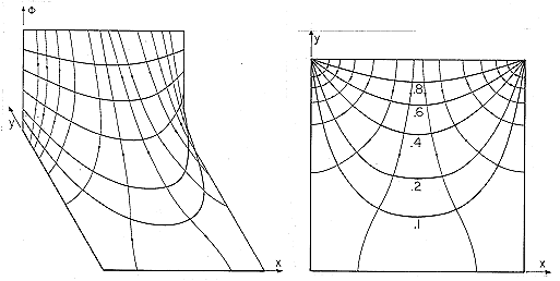
The potential given by (9) is illustrated in Fig. 5.5.3. In the three-dimensional portrayal, it is especially clear that the field is infinitely large in the corners where the driven electrode meets the grounded walls. Where the electric field emanates from the driven electrode, there is surface charge, so at the corners there is an infinite surface charge density. In practice, of course, the spacing is not infinitesimal and the fields are not infinite.
 Demonstration 5.5.1. Capacitance Attenuator
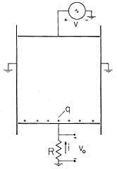
Because neither of the field laws in this chapter involve time derivatives, the field that has been determined is correct for v = v(t), an arbitrary function of time. As a consequence, the coefficients An are also functions of time. Thus, the charges induced on the walls of the box are time varying, as can be seen if the wall at y = 0 is isolated from the grounded side walls and connected to ground through a resistor. The configuration is shown in cross-section by Fig. 5.5.4. The resistance R is small enough so that the potential vo is small compared with v.
Figure 5.5.4 The bottom of the slot is replaced by an insulating electrode connected to ground through a low resistance so that the induced current can be measured. The charge induced on this output electrode is found by applying Gauss' integral law with an integration surface enclosing the electrode. The width of the electrode in the z direction is w, so
This expression is evaluated using (9).
Conservation of charge requires that the current through the resistance be the rate of change of this charge with respect to time. Thus, the output voltage is
and if v = V sin
t, then
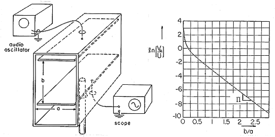
The experiment shown in Fig. 5.5.5 is designed to demonstrate the dependence of the output voltage on the spacing b between the input and output electrodes. It follows from (13) and (11) that this voltage can be written in normalized form as
Figure 5.5.5 Demonstration of electroquasistatic attenuator in which normalized output voltage is measured as a function of the distance between input and output electrodes normalized to the smaller dimension of the box. The normalizing voltage U is defined by (14). The output electrode is positioned by means of the attached insulating rod. In operation, a metal lid covers the side of the box Thus, the natural log of the normalized voltage has the dependence on the electrode spacing shown in Fig. 5.5.5. Note that with increasing b/a the function quickly becomes a straight line. In the limit of large b/a, the hyperbolic sine can be approximated by exp (n
b/a)/2 and the series can be approximated by one term. Thus, the dependence of the output voltage on the electrode spacing becomes simply
and so the asymptotic slope of the curve is -
.
Charges induced on the input electrode have their images either on the side walls of the box or on the output electrode. If b/a is small, almost all of these images are on the output electrode, but as it is withdrawn, more and more of the images are on the side walls and fewer are on the output electrode.
In retrospect, there are several matters that deserve further discussion. First, the potential used as a starting point in this section, (1), is one from a list of four in Table 5.4.1. What type of procedure can be used to select the appropriate form? In general, the solution used to satisfy the zero potential boundary condition on the "first" three surfaces is a linear combination of the four possible solutions. Thus, with the A's denoting undetermined coefficients, the general form of the solution is

Formally, (1) was selected by eliminating three of these four coefficients. The first two must vanish because the function must be zero at x = 0. The third is excluded because the potential must be zero at y = 0. Thus, we are led to the last term, which, if A4 = A, is (1).
The methodical elimination of solutions is necessary. Because the origin of the coordinates is arbitrary, setting up a simple expression for the potential is a matter of choosing the origin of coordinates properly so that as many of the solutions (16) are eliminated as possible. We purposely choose the origin so that a single term from the four in (16) meets the boundary condition at x = 0 and y = 0. The selection of product solutions from the list should interplay with the choice of coordinates. Some combinations are much more convenient than others. This will be exemplified in this and the following chapters.
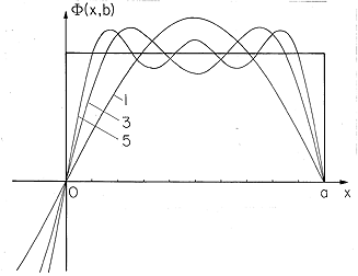
The remainder of this section is devoted to a more detailed discussion of the expansion in sinusoids represented by (9). In the plane y = b, the potential distribution is of the form

where the procedure for determining the coefficients has led to (8), written here in terms of the coefficients Vn of (17) as

The approximation to the
potential v that is uniform over the span of the driving electrode is
shown in Fig. 5.5.6. Equation (17) represents a square wave of period
2a extending over all x, - < x < +
 .
One half of a period appears
as shown in the figure. It is possible to represent this distribution
in terms of sinusoids alone because it is odd in x. In general, a
periodic function is represented by a Fourier series of both sines and
cosines. In the present problem, cosines were missing because the
potential had to be zero at x = 0 and x = a. Study of a Fourier
series shows that the series converges to the actual function in the
sense that in the limit of an infinite number of terms,

where  (x) is the actual potential distribution
and F(x) is the Fourier series approximation.
To see the generality of the approach exemplified here, we show that the orthogonality property of the functions X(x) results from the differential equation and boundary conditions. Thus, it should not be surprising that the solutions in other coordinate systems also have an orthogonality property.
In all cases, the orthogonality property is associated with any
one of the factors in a product solution. For the Cartesian problem
considered here, it is X(x) that satisfies boundary conditions at two
points in space. This is assured by adjusting the eigenvalue kn =
n /a so that the eigenfunction or mode, sin (n
 x/a), is zero
at x = 0 and x = a. This function satisfies (5.4.4) and the
boundary conditions.

The subscript m is used to recognize that there is an infinite number of solutions to this problem. Another solution, say the n-th, must also satisfy this equation and the boundary conditions.

The orthogonality property for these modes, exploited in evaluating the coefficients of the series expansion, is

To prove this condition in general, we multiply (20) by Xn and integrate between the points where the boundary conditions apply.

By identifying u = Xn and v = dXm/dx, the first term is integrated by parts to obtain

The first term on the right vanishes because of the boundary conditions. Thus, (23) becomes

If these same steps are completed with n and m interchanged, the result is (25) with n and m interchanged. Because the first term in (25) is the same as its counterpart in this second equation, subtraction of the two expressions yields

Thus, the functions are orthogonal provided that kn  km. For
this specific problem, the eigenfunctions are Xn = sin (n
 /a) and
the eigenvalues are kn = n
 /a.
But in general we can expect that our product
solutions to Laplace's equation in other coordinate systems will result
in a set of functions having similar orthogonality properties.


