In electroquasistatic field problems in which the boundary
conditions are specified on circular cylinders or on planes of
constant  , it is convenient to match these conditions with solutions
to Laplace's equation in polar coordinates (cylindrical coordinates
with no z dependence). The approach adopted is entirely analogous to
the one used in Sec. 5.4 in the case of Cartesian coordinates.
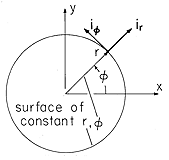
As a reminder, the polar coordinates are defined in Fig. 5.7.1. In these coordinates and with the understanding that there is no z dependence, Laplace's equation, Table I, (8), is

One difference between this equation and Laplace's equation written in Cartesian coordinates is immediately apparent: In polar coordinates, the equation contains coefficients which not only depend on the independent variable r but become singular at the origin. This singular behavior of the differential equation will affect the type of solutions we now obtain.
In order to reduce the solution of the partial differential
equation to the simpler problem of solving total differential
equations, we look for solutions which can be written as products of
functions of r alone and of  alone.

When this assumed form of  is introduced into (1), and the result
divided by
  and multiplied by r, we obtain

We find on the left-hand side of (3) a function of r alone and on
the right-hand side a function of  alone. The two sides of the
equation can balance if and only if the function of
  and the function
of r are both equal to the same constant. For this "separation
constant" we introduce the symbol -m2.


For m2 > 0, the solutions to the differential equation for F are conveniently written as

Because of the space-varying coefficients, the solutions to (5) are
not exponentials or linear combinations of exponentials as has so far
been the case. Fortunately, the solutions are nevertheless simple.
Substitution of a solution having the form rn into (5) shows that
the equation is satisfied provided that n =  m. Thus,

In the special case of a zero separation constant, the limiting solutions are

and

The product solutions shown in the first two columns of Table 5.7.1, constructed by taking all possible combinations of these solutions, are those most often used in polar coordinates. But what are the solutions if m2 < 0?
In Cartesian coordinates, changing the sign of the separation
constant k2 amounts to interchanging the roles of the x and y
coordinates. Solutions that are periodic in the x direction become
exponential in character, while the exponential decay and growth in the
y direction becomes periodic. Here the geometry is such that the r
and  coordinates are not interchangeable, but the new solutions
resulting from replacing m2 by -p2, where p is a real number,
essentially make the oscillating dependence radial instead of
azimuthal, and the exponential dependence azimuthal rather than radial.
To see this, let m2 = -p2, or m = jp, and the solutions given
by (7) become

These take a more familiar appearance if it is recognized that r can be written identically as

Introduction of this identity into (10) then gives the more familiar complex exponential, which can be split into its real and imaginary parts using Euler's formula.

Thus, two independent solutions for R(r) are the cosine and sine
functions of p ln r. The  dependence is now either
represented by \exp
  p
p or the hyperbolic functions that are
linear combinations of these exponentials. These solutions are
summarized in the right-hand column of Table 5.7.1.
In principle, the solution to a given problem can be approached by the methodical elimination of solutions from the catalogue given in Table 5.7.1. In fact, most problems are best approached by attributing to each solution some physical meaning. This makes it possible to define coordinates so that the field representation is kept as simple as possible. With that objective, consider first the solutions appearing in the first column of Table 5.7.1.
The constant potential is an obvious solution and need not be
considered further. We have a solution in row two for which the
potential is proportional to the angle. The equipotential lines and
the field lines are illustrated in Fig. 5.7.2a. Evaluation of the
field by taking the gradient of the potential in polar coordinates
(the gradient operator given in Table I) shows that it becomes
infinitely large as the origin is reached. The potential increases
from zero to 2 as the angle
  is increased from zero to
2
 . If the potential is to be single valued, then we cannot allow
that
  increase
further without leaving the region of validity of the solution. This
observation identifies the solution with a physical field observed when
two semi-infinite conducting plates are held at different potentials
and the distance between the conducting plates at their junction is
assumed to be negligible. In this case, shown in Fig. 5.7.2, the
outside field between the plates is properly represented by a
potential proportional to
  .
.
With the plates separated by an angle of 90 degrees rather than
360 degrees, the potential that is proportional to  is seen in the
corners of the configuration shown in Fig. 5.5.3.
The m2 = 0 solution in the third row is familiar from Sec. 1.3, for
it is the potential of a line charge. The fourth m2 = 0 solution is
sketched in Fig. 5.7.3.
In order to sketch the potentials corresponding to the solutions
in the second column of Table 5.7.1, the separation constant must be
specified. For the time being, let us assume that m is an integer.
For m = 1, the solutions r cos  and r sin
  represent
familiar potentials. Observe that the polar coordinates are related
to the Cartesian ones defined in Fig. 5.7.1 by
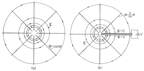
 =
=  , (b) region exterior to planar electrodes having
potential difference V.
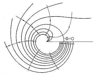
 =
=  , ln (r).


The fields that go with these potentials are best found by taking the gradient in Cartesian coordinates. This makes it clear that they can be used to represent uniform fields having the x and y directions, respectively. To emphasize the simplicity of these solutions, which are made complicated by the polar representation, the second function of (13) is shown in Fig. 5.7.4a.
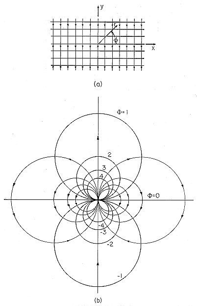
 = r sin
  ), (b)
  = r-1 , sin (
 ).
).
Figure 5.7.4b shows the potential r-1 sin  . To stay on a
contour of constant potential in the first quadrant of this figure as
 is increased toward
  /2, it is necessary to first increase
r, and then as
the sine function decreases in the second quadrant, to decrease r.
The potential is singular at the origin of r; as the origin is
approached from above, it is large and positive; while from below it is
large and negative. Thus, the field lines emerge from the origin
within 0 <
  <
<  and converge toward the origin in the lower
half-plane. There must be a source at the origin composed of equal
and opposite charges on the two sides of the plane r sin
  = 0.
The source, which is uniform and of infinite extent in the
z direction, is a line dipole.
This conclusion is confirmed by direct evaluation of the
potential produced by two line charges, the charge
- l situated at the origin, the charge
+
 l at a very small distance away from the
origin at r = d,
  =
=  /2. The potential follows from
steps paralleling
those used for the three-dimensional dipole in Sec. 4.4.

The spatial dependence of the potential is indeed sin  /r. In
an analogy with the three-dimensional dipole of Sec. 4.4, p
 \equiv
  l d is defined as the line dipole moment. In Example
4.6.3, it is shown that the equipotentials for parallel line charges
are circular cylinders. Because this result is independent of
spacing between the line charges, it is no surprise that the
equipotentials of Fig. 5.7.4b are circular.
In summary, the m = 1 solutions can be thought of as the fields of dipoles at infinity and at the origin. For the sine dependencies, the dipoles are y directed, while for the cosine dependencies they are x directed.
The solution of Fig. 5.7.5a,  \propto r2 sin 2
 , has
been met before in Cartesian coordinates. Either from a comparison of
the equipotential plots or by direct transformation of the Cartesian
coordinates into polar coordinates, the potential is recognized as
xy.
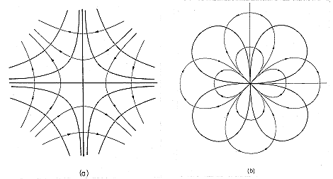
 = r2 sin (2
 ), (b)
  = r-2 sin (2
  ).
).
The m = 2 solution that is singular at the origin is shown in
Fig. 5.7.5b. Field lines emerge from the origin and
return to it twice as  ranges from 0 to 2
 . This
observation identifies four line
charges of equal magnitude, alternating in sign as the source of the
field. Thus, the m = 2 solutions can be regarded as those of
quadrupoles at infinity and at the origin.
It is perhaps a bit surprising that we have obtained from Laplace's equation solutions that are singular at the origin and hence associated with sources at the origin. The singularity of one of the two independent solutions to (5) can be traced to the singularity in the coefficients of this differential equation.
From the foregoing, it is seen that increasing m introduces a
more rapid variation of the field with respect to the angular
coordinate. In problems
where the region of interest includes all values of  , m must be an
integer to make the field return to the same value after one
revolution. But, m does not have to be an integer. If the region
of interest is pie shaped, m can be
selected so that the potential passes through one cycle over an
arbitrary interval of
  . For example, the periodicity angle can be
made
  o by making m
 o = n
o = n or m = n
 /
/ o,
where n can have any integer value.
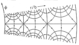
The solutions for m2 < 0, the right-hand column of Table 5.7.1, are illustrated in Fig. 5.7.6 using as an example essentially the fourth solution. Note that the radial phase has been shifted by subtracting p ln (b) from the argument of the sine. Thus, the potential shown is

and it automatically passes through zero at the radius r = b. The distances between radii of zero potential are not equal. Nevertheless, the potential distribution is qualitatively similar to that in Cartesian coordinates shown in Fig. 5.4.2. The exponential dependence is azimuthal; that direction is thus analogous to y in Fig. 5.4.2. In essence, the potentials for m2 < 0 are similar to those in Cartesian coordinates but wrapped around the z axis.

