Particular and Homogeneous Solutions to Poisson's and Laplace's Equations
 , satisfies the boundary conditions
  = 0 in
the planes y = +a and y = -a.

| (a) | What is  in this region? in this region?
|
| (b) | Identify  p and p and
 h. What boundary conditions are satisfied by h. What boundary conditions are satisfied by  h at
y = +a and y = -a? h at
y = +a and y = -a?
|
| (c) | Illustrate another combination of  p and p and
 h that could just as well be used and give the boundary
conditions that apply for h that could just as well be used and give the boundary
conditions that apply for  h in that case. h in that case.
|

 (x = 0) = 0 and
  (x =
d) = V, so
  =
=  (x) is independent of y and z.
| (a) | Show that Poisson's equation therefore reduces to
 |
| (b) | Integrate this expression twice and use the boundary
conditions to show that the potential distribution is
 |
| (c) | Argue that the first term in (c) can be  p, with the
remaining terms then p, with the
remaining terms then  h. h.
|
| (d) | Show that in that case, the boundary conditions satisfied by
 h are h are
 |

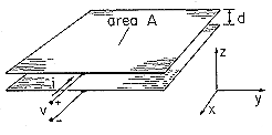
| (a) | Show that in the region well removed from the edges of the electrodes, the field E = -(v/d) iz satisfies Laplace's equation and the boundary conditions on the electrode surfaces. |
| (b) | Show that the
surface charge density on the lower surface of the upper electrode is
 s = s =  o v/d. o v/d.
|
| (c) | For a single pair of electrodes, the
capacitance C is defined such that q = Cv (13). Show that for the
plane parallel capacitor of Fig. P5.1.5, C = A o /d, where A is
the area of one of the electrodes. o /d, where A is
the area of one of the electrodes.
|
| (d) | Use the integral form of charge
conservation, (1.5.2), to show that i = dq/dt = Cdv/dt.
|
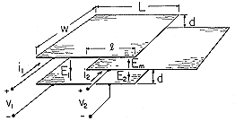
| (a) | Show that the fields denoted in the figure are then approximately E1 = v1/2d, E2 = v2/d and Em = (v1 - v2)/d. |
| (b) | Show that the net charges q1 and q2 on the top and
middle electrodes, respectively, are related to the voltages by the
capacitance matrix [in the form of (12)]
 |
Continuity Conditions
 a and
a and  b above and below
the plane y = 0 are

| (a) | Show that (4) holds. (The potential is continuous at y = 0.) |
| (b) | Evaluate E tangential to the surface y = 0 and show that it too is continuous. [Equation (1) is then automatically satisfied at y = 0.] |
| (c) | Use (5) to show that in the plane y = 0, the surface
charge density,  s = 2 s = 2 o o  V cos V cos  x, accounts for
the discontinuity in the derivative of x, accounts for
the discontinuity in the derivative of  normal to the plane y
= 0. normal to the plane y
= 0.
|
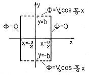
 guarantees the
continuity of tangential E [(4) implies that (1) is
satisfied], suppose that the potential is given in the plane y = 0:
 =
=  (x, 0, z).
| (a) | Which components of E can be determined from this information alone? |
| (b) | For example, if  (x, 0, z) = V sin ( (x, 0, z) = V sin ( x) sin
( x) sin
( z), what are those components of E? z), what are those components of E?
|

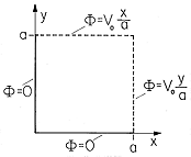
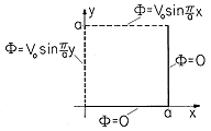
 in the z direction has the
square cross-section of dimensions as shown in Fig. P5.4.1. The walls
at x = 0 and y = 0 are at zero potential, while those at x = a
and y = a have
the linear distributions shown. The interior region is free of charge
density.
| (a) | Show that the potential inside is
 |
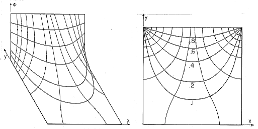
| (b) | Show that plots of  and E are as shown in the
first quadrant of Fig. 4.1.3. and E are as shown in the
first quadrant of Fig. 4.1.3.
|
 is zero at x = 0, then C =
0.
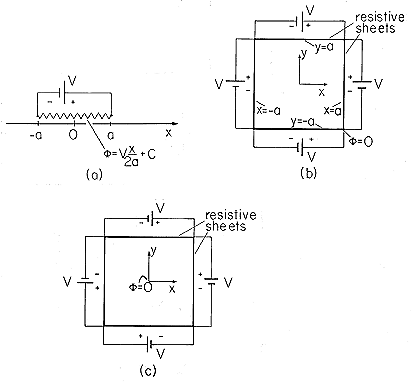
| (a) | Suppose a cylindrical region having a square
cross-section of
length 2a on a side, as shown in Fig. 5.4.2b, is constrained in
potential by resistive sheets and voltage sources, as shown. Note
that the potential is defined to be zero at the lower right-hand corner,
where (x, y) = (a, -a). Inside the cylinder, what must the potential be
in the planes x =  a and y = a and y =  a? a?
|
| (b) | Find the linear combination of
the potentials from the first column of Table 5.4.1 that satisfies the
conditions on the potentials required by the resistive sheets. That
is, if  takes the form takes the form
 |
| (c) | Determine E for this potential. |
| (d) | Sketch  and E. and E.
|
| (e) | Now the potential on the
walls of the square cylinder is constrained as shown in Fig. 5.4.2c.
This time the potential is zero at the location (x, y) = (0, 0). Adjust
the coefficients in (a) so that the potential satisfies these
conditions. Determine E and sketch the equipotentials and field
lines.
|
 z directions. There is no charge
density inside the cylinder, and the potentials on the boundaries are


| (a) | Show that the potential inside the cylinder is
 |
| (b) | Show that a plot of  and E is as given by the
part of Fig. 5.4.1 where - and E is as given by the
part of Fig. 5.4.1 where - /2 < kx < /2 < kx <  /2. /2.
|
 z directions is shown in Fig. P5.4.4. The
potentials on the boundaries are as shown.
| (a) | Inside the cylindrical space, there is no charge density.
Find  . .
|
| (b) | What is E in this region?
|
| (c) | Sketch  and E. and E.
|

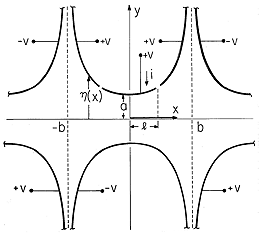
 is as shown in Fig. P5.4.5.
| (a) | Show that the potential in the region between the
electrodes is
 |
| (b) | Show that E in this region is
 |
| (c) | Show that plots of  and E are as shown in
Fig. 5.4.2. and E are as shown in
Fig. 5.4.2.
|
| (d) | Show that the net charge on the upper electrode segment
between y = -l and y = l is
 |
| (e) | Given that v(t) = Vo sin  t, where Vo and t, where Vo and
 are constants, show that the current to the electrode segment
i(t), as defined in Fig. P5.4.5, is are constants, show that the current to the electrode segment
i(t), as defined in Fig. P5.4.5, is
  |
| (a) | Find  in the region
between the electrodes. in the region
between the electrodes.
|
| (b) | Determine E. |
| (c) | Sketch  and E. and E.
|
| (d) | Find the charge q on the electrode segment in the upper middle electrode. |
| (e) | Given that v(t) = Vo cos  t, what is i(t)? t, what is i(t)?
|
Modal Expansion to Satisfy Boundary Conditions
 d (x).
The plates and short have zero potential.
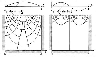
| (a) | Show that, in terms of
 d (x), the potential distribution for 0 < y < b, 0 < x < a is d (x), the potential distribution for 0 < y < b, 0 < x < a is
  |
| (b) | In particular, if the imposed
potential is as shown in Fig. P5.5.1b, show that An is
 |
In particular, suppose that these distributions of potential are uniform, so that V1(x) = Va and V2(y) = Vb, with Va and Vb defined to be independent of x and y.
| (a) | The region inside the cylinder is free space. Show that the potential distribution there is
 |
| (b) | Show that the distribution of surface charge density along the
wall at x = a is
 |
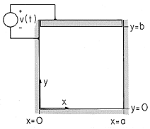
| (a) | Determine the potential in the free space region inside the cylinder. |
| (b) | Find the surface charge distribution on the wall at y =
b.
|
| (a) | The electrodes extend to infinity in the -x direction. Show that, far to the left, the potential between the electrodes
tends to
 |
| (b) | Using this result as a part of the solution,  a, the
potential between the plates is written as a, the
potential between the plates is written as
 = =  a + a +  b. Show that the boundary conditions that
must be satisfied by b. Show that the boundary conditions that
must be satisfied by  b are b are
   |
| (c) | Show that the potential between the electrodes is
 |
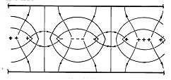
| (d) | Show that a plot of  and E appears as shown in
Fig. 6.6.9c, turned upside down. and E appears as shown in
Fig. 6.6.9c, turned upside down.
|

 d(x).
d(x).
| (a) | What is the potential distribution between the plates far to the left? |
| (b) | If  is taken as the potential is taken as the potential  a that
assumes the correct distribution as y a that
assumes the correct distribution as y  - - , plus a
potential , plus a
potential  b, what boundary conditions must be satisfied by b, what boundary conditions must be satisfied by
 b? b?
|
| (c) | What is the potential distribution between the plates? |
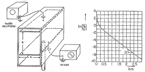
 = (Vy/b) +
  1.
1.
| (a) | Show that the boundary conditions that
must be satisfied by  1 are that 1 are that  1 = -Vy/b at x = 0
and at x = a, and 1 = -Vy/b at x = 0
and at x = a, and  1 = 0 at y = 0 and y = b. 1 = 0 at y = 0 and y = b.
|
| (b) | Show that the potential is
  |
 o. On the upper boundary, the
potential is
  (x, d, z) = Va sin (
 x). On the lower boundary,
 (x, 0, z) = Vb sin (
 x). Show that
  (x, y, z)
throughout the region 0 < y < d is

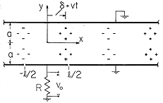
 o, but the
potential at y = d is
  =
=  o sin (kx), while that at y =
0 is zero (
 o and k are given constants). Find
  in the
region where 0 < y < d, between the boundaries.
 d/2 in Fig.
P5.6.3, the charge density is

 o and
o and  are given constants. Electrodes at
y =
  d/2 constrain the tangential electric field there to be

| (a) | Show that a particular solution is
 |
| (b) | Show that the total potential is the sum of this solution
and that solution to Laplace's equation that makes the total solution
satisfy the boundary conditions.
 |
| (c) | The force density (force per unit volume) acting on the
charge is  E. Show that the force fx acting on a section
of the charge of length in the x direction E. Show that the force fx acting on a section
of the charge of length in the x direction  = 2 = 2 /k
spanning the region -d/2 < y < d/2 and unit length in the z
direction is /k
spanning the region -d/2 < y < d/2 and unit length in the z
direction is
 |
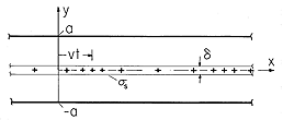

 o and
o and  are constants. Electrodes at y = d
constrain the potential there to be
  (x, d) = Vo cos (kx)
(Vo and k given constants), while an electrode at y = 0 makes
 (x, 0) = 0.
| (a) | Find a particular solution that satisfies Poisson's equation everywhere between the electrodes. |
| (b) | What boundary conditions must the homogeneous solution satisfy at y = d and y = 0? |
| (c) | Find  in the region 0 < y < d. in the region 0 < y < d.
|
| (d) | The force density (force per unit volume) acting on the
charge is  E. Find the total force fx acting on a section
of the charge spanning the system from y = 0 to y = d, of unit
length in the z direction and of length E. Find the total force fx acting on a section
of the charge spanning the system from y = 0 to y = d, of unit
length in the z direction and of length  = 2 = 2 /k in the
x direction. /k in the
x direction.
|
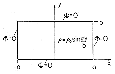
 z directions has a
rectangular cross-section of dimensions 2a and b, as shown in Fig.
P5.6.5. The boundaries are at zero potential while the region inside
has the distribution of charge density

 o is a given constant. Show that the potential in this
region is

| (a) | Given that a particular solution inside the boundaries is
  are given constants, what is the charge density
in that region? are given constants, what is the charge density
in that region?
|
| (b) | What is  ? ?
|
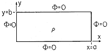
 o x/l. Determine
  inside the box, given that
  = 0
on the walls.
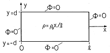
 =
=  o
cos (
 x) e
x) e y, where
  o,
o,  , and
, and  are
positive constants. In region (a), where 0 < y,
  = 0.
= 0.
| (a) | Show that a particular solution in the region y < 0 is
 |
| (b) | There is no surface charge density in the plane y = 0.
Show that the potential is
 |
 s =
s =
 o sin
o sin  (x - xo) is in the plane y = 0, as shown
in Fig. 5.6.3. At a distance a above and below the sheet, electrode
structures are used to constrain the potential to be
  = V cos
 x. The system extends to infinity in the x and z
directions. The regions above and below the sheet are designated (a)
and (b), respectively.
| (a) | Find  a and a and  b in terms of the constants V, b in terms of the constants V,
 , ,  o, and xo. o, and xo.
|
| (b) | Given that the force per unit area acting on the charge
sheet is  s Ex (x, 0), what is the force acting on a section
of the sheet having length d in the z direction and one
wavelength 2 s Ex (x, 0), what is the force acting on a section
of the sheet having length d in the z direction and one
wavelength 2 / / in the x direction? in the x direction?
|
| (c) | Now, the potential on
the wall is made a traveling wave having a given angular frequency
 , ,  (x, (x,  a, t) = V cos ( a, t) = V cos ( x - x -  t),
and the charge moves to the right with a velocity U, so that t),
and the charge moves to the right with a velocity U, so that
 s = s =  o sin o sin  (x - Ut - xo), where U = (x - Ut - xo), where U =  /
/ . Thus, the
wall potentials and surface charge density move in synchronism.
Building on the results from parts (a)-(b), what is the potential
distribution and hence total force on the section of charged sheet? . Thus, the
wall potentials and surface charge density move in synchronism.
Building on the results from parts (a)-(b), what is the potential
distribution and hence total force on the section of charged sheet?
|
| (d) | What you have developed is a primitive model for an
electron beam
device used to convert the kinetic energy of the electrons
(accelerated to the velocity v by a dc voltage) to high-frequency
electrical power
output. Because the system is free of dissipation, the electrical power
output (through the electrode structure) is equal to the mechanical
power input. Based on the force found in part (c), what is the
electrical power output produced by one period 2 / / of the
charge sheet of width w? of the
charge sheet of width w?
|
| (e) | For what values of xo would the device act as a generator of electrical power? |
Solutions to Laplace's Equation in Polar Coordinates
 = V
sin 5
 . The regions r < a and a < r are free of charge
density. Show that the potential is

 measured
relative to the x axis and z the third coordinate axis, the
potential on the surface at r = R is constrained by segmented
electrodes there to be
  = V sin
  .
.
| (a) | If  = 0 in the region r < R, what is = 0 in the region r < R, what is  in that region? in that region?
|
| (b) | Over the range r < R, what is the surface charge density on the surface at y = 0? |
 = 0 is bounded from outside
at r = a by a surface having the potential
  = Va cos 3
 and from the inside at r = b by a surface having the potential
  = Vb sin
  . Show that
  in the annulus can be written
as the sum of two terms, each a combination of solutions to Laplace's
equation designed to have the correct value at one radius while being
zero at the other.

 <
<  ,
,  = 0. On the
boundaries of this region at r = a, at
  = 0 and
  =
=  ,
,  = 0. At r = b,
  = Vb sin (
 /
/ ).
Determine
  in this region.
 <
<  ,
,  = 0. On the
boundaries of this region at r = a, r = b and at
  = 0,
= 0,
 = 0. At
  =
=  , the potential is
  = V sin
[3
 ln(r/a)/ln(b/a)]. Show that within the region,

 = 0 is at potential
  = V, while that at
  =
3
=
3 /2 is at zero potential. The system extends to infinity in the
 z and r directions. Determine and sketch
  and E
in the range 0 <
  < 3
< 3 /2.
/2.
Examples in Polar Coordinates
 and E as given by (4) and (5), respectively,
describe the potential and electric field intensity around a perfectly
conducting half-cylinder at r = R on a perfectly conducting plane at
x = 0 with a uniform field Ea ix applied at x
 . Show that the maximum field intensity is twice that of the
applied field, regardless of the radius of the half-cylinder.
 = Vb > 0. On the outer surface, where r = a,
  = Va >
0.
| (a) | What is  in the annular region? in the annular region?
|
| (b) | How large must Vb be to insure that all lines of E are outward directed from the inner cylinder? |
| (c) | What is the net charge per unit length on the inner cylinder under the conditions of (b)? |
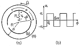
 of a shaft is shown in Fig. P5.8.3a. A
cylindrical grounded electrode has radius R. (The
resistance Ro is "small.") Outside and concentric at r = a is a
rotating shell supporting the surface charge density distribution
shown in Fig. P5.8.3b.
| (a) | Given  o and o and  o, show that in regions (a) and
(b), respectively, outside and inside the rotating shell, o, show that in regions (a) and
(b), respectively, outside and inside the rotating shell,
 |
| (b) | Show that the charge on the segment of the inner electrode
attached to the resistor is

|
| (c) | Given that  o = o =  t, show that the output
voltage is related to t, show that the output
voltage is related to  by by
  . .
|
 = 0 and the other in the plane
 =
=  . They essentially extend to infinity in the
  z
directions. Closing the region between the electrodes at r = R is an
electrode having potential V. Show that the potential inside the
region bounded by these three surfaces is

 = 0 plane by a grounded electrode and in the
  =
=
 plane by one that has
  = V. The region extends to
infinity in the r direction. At r = R,
  = V. Determine
 .
.
 = 0 that reaches from
the wall to the center. The gaps between the cylinder and the fin are
very small.
| (a) | Find all solutions in polar coordinates that satisfy
the boundary conditions at  = 0 and = 0 and  = 2 = 2 . Note
that you cannot accept solutions for . Note
that you cannot accept solutions for  of negative powers in
r. of negative powers in
r.
|
| (b) | Match the boundary condition at r = R. |
| (c) | One of the terms in this solution
has an electric field intensity that is infinite at the tip of the
fin, where r = 0. Sketch  and E in the neighborhood of the
tip. What is the and E in the neighborhood of the
tip. What is the  s on the fin associated with this term as
a function of r? What is the net charge associated with this term? s on the fin associated with this term as
a function of r? What is the net charge associated with this term?
|
| (d) | Sketch the potential and field intensity throughout the region. |
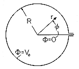
 = 0 has the
potential v. The wall at
  =
=  o is grounded. Determine the
interior potential.
Three Solutions to Laplace's Equation in Spherical Coordinates
 = V cos
  .
.
| (a) | With no charge density either outside
or inside this shell, what is  for r < a and for r > a? for r < a and for r > a?
|
| (b) | Sketch  and E. and E.
|
 o cos
o cos  .
.
| (a) | Show that if this is the only charge in the
volume of interest, the potential is
 |
| (b) | Show that a plot of  and E appears as shown in
Fig. 6.3.1. and E appears as shown in
Fig. 6.3.1.
|
 =
=  o cos
o cos  . Show that the
potential there is

 =
=  o (r/a)m cos
  , where
  o and m
are given constants. If the potential
  = 0 at r = a, what is
 for r < a?
Three-Dimensional Solutions to Laplace's Equation
 = v.
Show that


 s =
s =  o sin (
 x/a) sin (
 z/w). Find the
potentials
  a and
a and  b above and below this surface,
respectively.
 =
=  o. Write four essentially
different expressions for the potential distribution.

