Configurations composed of subregions where the material has uniform properties are already familiar from Secs. 6.6 and 7.5. The conductivity and permittivity are then step functions of position, and the terms on the right in (7.8.4) are spatial impulses. Thus, the charge density tends to accumulate at interfaces between regions and is represented by a surface charge density.
We consider first the evolution of the potential distribution in a region having uniform properties. With the inhomogeneities represented by the continuity conditions, the discussion is then extended to piece-wise uniform configurations.
Fields in Regions Having Uniform Properties
Where  and
and  are uniform, (7.8.7) becomes

This expression is satisfied either if the potential obeys the relaxation equation

or if it satisfies Laplace's equation

In general, the potential is a linear combination of these solutions.

The potential satisfying (2) is that associated with the relaxation
of the charge density initially distributed in the volume of the
material. We can think of this as being a particular solution, because
the divergence of the associated electric displacement D =  E =
-
E =
-

 p gives the unpaired charge density, (7.7.4), at each
point in the volume V for t > 0. The solutions
  h to
Laplace's equation can then be used to make the sum of the two solutions
satisfy the boundary conditions.
Given that the initial charge density throughout the volume is  i
(r), the subsequent distribution is given by (7.7.4). One
particular solution for the potential that then satisfies
Poisson's equation throughout the volume follows from evaluating the
superposition integral [(4.5.3) with
  o
o 
 ] over that
volume.

Note that this potential indeed satisfies (2) and the initial conditions on the charge density in the volume. Of course, the integral could be extended to charges outside the volume V, and the particular solution would be equally valid.
The solutions to Laplace's equation make it possible to make the total potential satisfy boundary conditions. Because an initial distribution of volume charge density cannot be initiated by means of boundary electrodes, the decay of an initial charge density is not usually of interest. The volume potential is most often simply a solution to Laplace's equation. Before delving into these more common examples, consider one that illustrates the more general situation.
Example 7.9.1. Potential Associated with Relaxation of Volume Charge
In Example 7.7.1, the decay of charge having a spherical distribution in space was described. This could be done without regard for boundary constraints. To determine the associated potential, we stipulate the nature of the boundary surrounding the uniform material in which the charge is initially embedded.
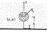
The uniform material fills the upper half-space and is bounded in the plane z = 0 by a perfect conductor constrained to zero potential. As shown in Fig. 7.9.1, when t = 0, there is an initial distribution of charge density that is uniform and of density
o throughout a spherical region of radius a centered at z = h on the z axis, where h > a.
Figure 7.9.1 Infinite half-space of material having uniform conductivity and permittivity is bounded from below by a perfectly conducting plate. When t = 0, there is a uniform charge density in a spherical region. In terms of a spherical coordinate system centered on the z axis at z = h, a particular solution for the potential follows from the integral form of Gauss' law, much as in Example 1.3.1. With r+ denoting the radial distance from the center of the spherical region,
where r+ = [x2 + y2 + (z - h)2]1/2 and


/
.
Note that this potential satisfies (2) and the initial condition but does not satisfy the zero potential condition at z = 0. To satisfy the latter, we add a potential that is a solution to Laplace's equation, (3), everywhere in the upper half-space. This is the potential associated with an image charge density -
o exp (-t/
) distributed uniformly over a spherical region of radius a centered at z = -h.
where r- = [x2 + y2 + (z + h)2]1/2, z > 0.
Thus, the total potential
=
p +
h that satisfies both the initial conditions and boundary conditions for 0 < t is
At each instant in time, the potential distribution is the same as if the charge and its image were static. As the charge relaxes, so does its image. Note that the charge relaxes to the boundary without producing a net charge density anywhere outside the spherical region where the charge was initiated.
Continuity Conditions in Piece-Wise Uniform Systems
Where the material properties undergo step discontinuities, the differential equations are represented by continuity conditions. The one representing the condition that the field be irrotational, (7.8.6), is the same as that in Sec. 5.3.

The continuity condition representing Gauss' law, (7.7.2), is also familiar (6.2.16).

The continuity condition representing charge conservation, (7.7.1), is (1.5.12). With the current density expressed in terms of Ohm's law, this continuity condition becomes

For the incremental volume of Fig. 7.9.2, this continuity condition requires that if the conduction current entering the volume from region (b) exceeds that leaving to region (a), there must be an increasing surface charge density within the volume.
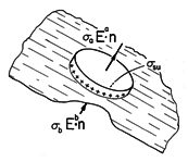
The fact that we are solving a second-order differential equation, (7.8.7), suggests that there are really only two continuity conditions. Thus, Gauss' continuity condition only serves to relate the field to the unknown surface charge density, and the combination of (10) and (11) comprise one continuity condition.

This continuity condition and the one on the tangential field or potential, (9), are needed to splice together solutions representing fields in piece-wise uniform configurations.
The following example illustrates how the time dependence of the continuity condition allows the fields and charge distribution to evolve from the distributions for perfect dielectrics described in the latter part of Chap. 6 to the steady conduction distributions discussed in the first part of this chapter.
Example 7.9.2. Maxwell's Capacitor
A configuration that brings out the roles of polarization and conduction in the field evolution while avoiding geometric complications is shown in Fig. 7.9.3. The space between perfectly conducting parallel plates is filled by layers of material. The one above has thickness a, permittivity
a, and conductivity
a, while for the one below, these parameters are b,
b, and
b, respectively. When t = 0, a switch is closed and the potential V of a battery is applied across the two electrodes. Initially, there is no unpaired charge between the electrodes either in the volume or on the interface.
Figure 7.9.3 Maxwell's capacitor. The electrodes are assumed long enough so that the fringing can be neglected and the fields in each of the materials taken as uniform.
The linear potential associated with this distribution satisfies Laplace's equation, (3). Because there is no initial charge density in the volumes of the layers, the particular part of the potential, the solution to (2), is zero.
The voltage source imposes the condition that the line integral of the electric field between the plates must be equal to v(t).
Because the layers are conducting, they respond to the application of the voltage with conduction currents. Since the currents differ, they cause a time rate of change of unpaired surface charge density at the interface between the layers, as expressed by (12).
Note that the boundary conditions on tangential E at the electrode surfaces and at the interface are automatically satisfied.
Given the driving voltage, these last two expressions comprise two equations in the two unknowns Ea and Eb. Thus, the solution to (14) for Eb and substitution into (15) gives a first-order differential equation for the field response in the upper layer.
In particular, consider the response to a step in voltage, v = V u-1(t). The drive on the right in (16) then consists of a step and an impulse. The impulse must be matched by an impulse on the left. That is, the field Ea also undergoes a step change when t = 0. To identify the magnitude of this step, integrate (16) from 0- to 0+.
The result is a relationship between the jumps in voltage and in field.
Because v(0-) = 0 and Ea(0-) = 0, it follows that
For t > 0, the particular plus homogeneous solution to (16) is
where
The coefficient A is adjusted to make Ea meet the initial condition given by (19). Thus, the field transient in the upper layer is found to be
It follows from (14) that the field in the lower layer is then
The unpaired surface charge density, (10), follows from these fields.
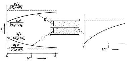
The field and unpaired surface charge density transients are shown in Fig. 7.9.4. The curves are drawn to depict a lower layer that has a somewhat greater permittivity and a much greater conductivity than the upper layer. Just after the step in voltage, when t = 0+, the surface charge density remains zero. Thus, the electric fields are at first what they would be if the layers were regarded as perfectly insulating dielectrics. As the surface charge accumulates, these fields approach values consistent with steady conduction. The limiting surface charge density approaches a saturation value that could be found by first evaluating the steady conduction fields and then finding
su. Note that this surface charge can be positive or negative. With the lower region much more conducting than the upper one (
b
a

a
b) the surface charge is positive. In this case, the field ends up tending to be shielded out of the lower layer.
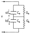
Figure 7.9.4 With a step in voltage applied to the plane parallel configuration of Fig. 7.9.3, the electric field intensity above and below the interface responds as shown on the left, while the unpaired surface charge density has the time dependence shown on the right. Piece-wise continuous configurations can often be represented by capacitor-resistor networks. An exact circuit representation of Maxwell's capacitor is shown in Fig. 7.9.5. The voltages across the capacitors are simply va = Ea a and vb = Eb b. In the circuit, the surface charge density given by (23) is the sum of the net charge per unit area on the lower plate of the top capacitor and that on the upper plate of the lower capacitor.
Nonuniform Fields in Piece-Wise Uniform Systems
We continue now to consider examples with no initial charge density in the regions having uniform conductivity and dielectric constant. Since it is not possible to establish a charge density in these regions by means of boundary constraints, this is almost always the situation in practice. The field distributions in the uniform subregions have potentials that satisfy Laplace's equation, (3). These are "spliced" together at the interfaces between regions and constrained at boundaries by conditions that vary with time. The continuity conditions vary with time to account for the accumulation of unpaired charge at the interfaces between regions.
Maxwell's capacitor, Example 7.9.2, illustrates most features of the surface charge relaxation process. The response to a step function of voltage across an electrode pair is at first the field distribution of a system of perfect dielectrics, as developed in Chap. 6. After many charge relaxation times, steady conduction prevails, and the fields are as described in Sec. 7.5. In the remainder of this section, configurations will be considered that, by contrast to Maxwell's capacitor, have fields that change their shape as the relaxation process evolves.
The interplay of polarization and conduction processes is also evident in the sinusoidal steady state response of a system. Just as the Maxwell capacitor has short-time and long-time responses dominated by the "capacitors" and "resistors," respectively, the high-frequency and low-frequency responses are dominated by polarization and conduction, respectively. This too will now be illustrated.
Example 7.9.3. Spherical Semi-insulating Material Embedded in a Second Material Stressed by Uniform Electric Field
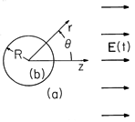
An electric field intensity E(t) is imposed on a material having permittivity and conductivity (
a ,
a), perhaps by means of plane parallel electrodes. At the origin of a spherical coordinate system embedded in this material is a spherical region having permittivity and conductivity (
b ,
b) and radius R, as shown in Fig. 7.9.6. Limiting cases include a conducting sphere surrounded by free space (
a =
o ,
a = 0) or an insulating spherical cavity surrounded by a conducting material (
b = 0).
Figure 7.9.6 A spherical material with conductivity band permittivity
b is surrounded by a material with conductivity and permittivity
a,
a). An electric field E(t) that is uniform far from the sphere is applied.
In each of the regions, the potential must satisfy Laplace's equation. From our experience with the potentials for perfect dielectric and for steady conduction configurations, we can expect that the boundary conditions can be satisfied using combinations of uniform and dipole fields. With the understanding that the coefficients A(t) and B(t) are functions of time, the solutions to Laplace's equation are therefore postulated to take the form
Note that the uniform part of the exterior field has been matched at r

to the given driving field.
Continuity of the tangential electric field at r = R, (9), requires that these potential functions match at r = R.
Conservation of charge, with the surface charge density represented using Gauss' law, (12), makes the further requirement that
In substituting the potentials of (24) into these two conditions, no derivatives with respect to
are taken, so each term has the
dependence cos (
). It is for this reason that such a simple solution can be used to satisfy the continuity conditions. Substitution into (25) relates the coefficients
and with this relation used to eliminate B, substitution into (26) results in a differential equation for A(t), with E(t) as a driving function.
Step Response
Note that expression (28) has the same form as that for Maxwell's capacitor, (16). The procedure leading to the field response to a step function of applied field, E = Eo u-1(t), is therefore identical to that illustrated in Example 7.9.2. In fact, comparison of these equations makes it clear that the required solution, given that there were no initial fields (when t = 0-), is
where the relaxation time
= (2
a +
b)/(2
a +
b). The coefficient B follows from (27). Thus, the potential of (24) is determined for t
0.
The accumulation of unpaired surface charge at r = R accounts for the redistribution of potential with time. It follows from (10) that
Thus, the unpaired surface charge density accumulates at the poles of the sphere, exponentially approaching a saturation value at a rate determined by the relaxation time
. Just after the field is turned on, this surface charge density is zero and the field distribution should be that for a uniform field applied to perfect dielectrics. Indeed, evaluated when t = 0, (30) gives the potential for perfect dielectrics. In the opposite extreme, where many relaxation times have passed so that the exponentials in (30) are negligible, the potential assumes the distribution for steady conduction.
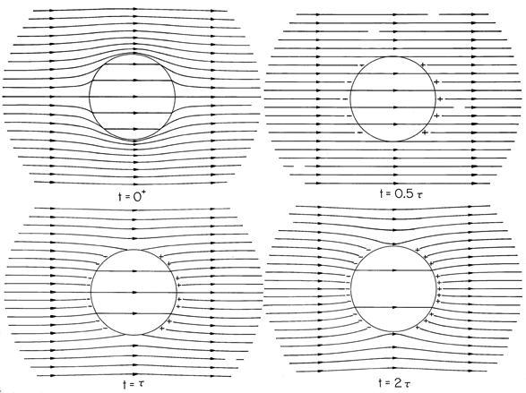
A graphical portrayal of this field transient is given in Fig. 7.9.7. The case shown was chosen because it involves a drastic redistribution of the field as time progresses. The spherical region is highly conducting compared to its surroundings, but the exterior material is highly polarizable compared to the spherical region. Thus, just after the switch is closed, the field lines tend to be trapped in the outer region. As time progresses and conduction rules, these lines tend to pass through the highly conducting sphere. The temporal scale of the transient is determined by the relaxation time
.
Figure 7.9.7Evolution of the displacement flux density D in and around the sphere of Fig. 7.9.6 and of su in response to the application of a step in applied field. The sphere is more conducting than its surroundings (
a /
b = 0.2), while the outer region has a greater permittivity than the inner one,
a /
b = 5. Thus, when the distribution of D is determined by the polarization just after the field is applied, the field lines tend to be trapped in the outer region. By the time t = 0.5,
, enough
su has been induced to cancel the field associated with
sp, and the electric field intensity is essentially uniform. In the final state, conduction alone determines the distribution of E. However, it is D that is shown in the figure, so, in fact, the permittivities do contribute to the final relative intensities.
Sinusoidal Steady State Response
Consider now the sinusoidal steady state that results from applying the uniform field
As in dealing with ac circuits, where the currents and voltages are also solutions to constant coefficient ordinary differential equations, the response is now assumed to have the same frequency
as the drive but to have a yet to be determined amplitude and phase represented by the complex coefficients A and B.
Substitution of (32) and (33a) into (28) gives an expression that can be solved for
in terms of the drive, Ep.
In turn, the complex amplitude B follows from this result and (27).
Now, with the amplitudes in (31) and (32) given by these expressions, the sinusoidal steady state fields postulated with (24) are determined.
The surface charge density associated with these fields is then
With the frequency rather than the time as the parameter, these expressions can be interpreted analogously to the step function response, (30) and (31). In the high-frequency limit, where
the conductivity terms become negligible in (36), the coefficients
and
become independent of frequency and real. Thus, the fields are in temporal phase with the applied field and sinusoidally varying versions of what would be found if the materials were assumed to be perfect dielectrics. If the frequency is high compared to the reciprocal charge relaxation times, the field distributions are the same as they would be just after a step in applied field [when t = 0+ in (30)].
With the inequalities of (38) reversed, the terms involving the permittivity in (36) are negligible, the coefficients
and
are again real and hence the fields are just as they would be for stationary conduction except that they vary sinusoidally with time. Thus, in the low frequency limit, the fields are sinusoidally varying versions of the steady conduction fields that prevail long after a step in applied field [(30) in the limit t

].
These high- and low-frequency limits are consistent with the frequency dependence of the unpaired surface charge density, given by (37). At low frequencies, this surface charge density varies sinusoidally in or out of phase with the applied field and with an amplitude consistent with steady conduction. As the frequency is made to greatly exceed the reciprocal relaxation time, the magnitude of this charge falls to zero. In this high-frequency limit, there is insufficient time during one cycle for significant charge to relax to the spherical interface. Thus, at high frequencies the fields become the same as if the unpaired charge density were ignored and the dielectrics assumed to be perfectly insulating.
In the two demonstrations that close this section, an obvious objective is the association of the previous example with practical situations. The approximations used to rederive the relevant fields cast further light on the physical processes at work.
Demonstration 7.9.1
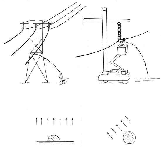
Capacitively Induced Fields in a Person in the Vicinity of a High-Voltage Power LineA person standing under a conventional power line, as in Fig. 7.9.8a, is subject to a 60 Hz alternating electric field intensity that is typically 5 x 10⁴ v/m. In response to this field, body currents are induced. Common experience suggests that these are not large enough to create discomfort, but are the currents appreciable enough to be of long-term medical concern?
Figure 7.9.8 (a) Person in vicinity of power line terminates lines of electric field intensity and hence is subject to currents associated with induced charge. The electric field intensity at the ground is as much as 5 x 10⁴ V/m. (b) Worker carrying out "bare-handed maintenance" is subject to field that depends greatly on shielding provided, but can be 5 x 10⁵ V/m or more. (c) Hemispherical model for person on ground in (a). (d) Spherical model for person near line without shielding, (b). In the bare-handed maintenance of power lines, a person is brought to within arms length of the line by an insulated hoist, as shown in Fig. 7.9.8b. Without shielding, the body is in this case subjected to much more intense fields, perhaps 5 x 10⁵ v/m. For the first person proving out this technique, the estimation of fields and currents within the body was of considerable interest.
To the layman, these imposed fields seem to imply that a body one meter in length would be subject to a voltage difference of 50 kV at the ground and 500 kV near the line. However, as we will now illustrate, surrounded by air, the body does an excellent job of shielding out the electric field.
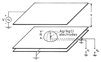
The hemispherical conductor resting on a ground plane, shown in Fig. 7.9.9, is a model for an individual on (and in electrical contact with) the ground. In the experiment, the hemisphere is jello, molded to have the radius R and having a conductivity essentially that of the salt water used in its making. (To obtain the physiological conductivity of 0.2 S/m, unflavored gelatine is made using 0.02 M NaCl, a solution of 1.12 grams/liter.)
Figure 7.9.9 Demonstration of currents induced in flesh-simulating hemisphere by field applied in surrounding air. Presumably, the potential in and around the hemisphere is given by (30). The z = 0 plane is at zero potential for the spherical region described, and so the potential applies equally well to the hemisphere on the ground plane. Parameters are (
a,
a) = (
o , 0) in the air and (
b,
b) = (
,
) in the hemisphere. A conductivity typical of physiological tissue is
= .2 S/m. As a result, the charge relaxation time based on the permittivity of the body (
b = 81
o) and the conductivity of the body is extremely short,
= 4 x 10⁻⁹ s. This makes it possible to approximate the potential distribution using the two simple steps that follow.
First, because the charge can relax to the surface in a time that is far shorter than 1/
, and because the hemisphere is surrounded by material that has far less conductivity, as far as the field in the air is concerned, its surface is an equipotential.
Thus, the potential distribution can be written by inspection [or by recourse to (5.9.7)] as
Because of the short relaxation time and high conductivity for the sphere relative to the air, the surface charge density is essentially determined by the exterior field. Thus, the conservation of charge continuity condition, (12), is approximately
The rate of change of the surface charge density on the right in this expression has already been determined, so the expression serves to evaluate the normal conduction current density just inside the hemispherical surface.
In the interior region, the potential is uniform and thus takes the form Br cos (
). Evaluation of the coefficient B by using (42) then gives the approximate potential distribution within the hemisphere.
In retrospect, note that the potentials given by (40) and (43) are obtained by taking the appropriate limit of the potential obtained without making approximations, (36).
Inside the hemisphere, the conditions for essentially steady conduction prevail. Thus, the potential predicted by (43) is probed by means of metal spheres (Ag/AgCl electrodes) embedded in the jello and connected to an oscilloscope through insulated wires. Inside the hemisphere, surface charge stored on the surfaces of the insulated wires has a minor effect on the current distribution.
Typical experimental values for a 250 Hz excitation are R = 3 .8 cm, s = 12.7 cm, v = 565 V peak, and
= 0.2 S/m. With the probes located at z = 2.86 cm and z = 0.95 cm, the measured potentials are 25
V peak and 10
V peak, respectively. With the given parameters, (43) gives 26.5
V peak and 8.8
V peak, respectively.
What are the typical current densities that would be induced in a person in the vicinity of a power line? According to (41), for the person on the ground in a field of 5 x 10⁴ V/m (Fig. 7.9.8a), the current density is Jz =
Ez = 0.05
A/cm2. For the person doing bare-handed maintenance where the field is perhaps 5 x 10⁵ V/m (Fig. 7.9.8b), the model is a sphere in a uniform field (Fig. 7.9.8d). The current density is again given by (43), Jz =
Ez = 0.5
A/cm2.
Of course, the geometry of a person is not spherical. Thus, it can be expected that the field will concentrate more in the actual situation than for the hemispherical or spherical models. The approximations introduced in this demonstration would greatly simplify the development of a numerical model.
Have we found estimates of current densities suggesting danger, especially for the maintenance worker? Physiological systems are far too complex for there to be a simple answer to this question. However, matters are placed in some perspective by recognizing that currents of diverse origins exist in the body so long as it lives. In the next demonstration, electrocardiogram potentials are used to estimate current densities that result from the muscular contractions of the heart. The magnitude of the current density found there will lend some perspective to that determined here.
The approximate analysis introduced in support of the previous demonstration is an example of the "inside-outside" viewpoint introduced in Sec. 7.5. The exterior insulating region, where the field was applied, was "inside," while the interior conducting region was "outside." The following demonstration continues this theme with a contrasting example, where the excitation is in the conducting region.
Demonstration 7.9.2. Currents Induced by the Heart
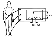
The configuration for taking an electrocardiogram is typically as shown in Fig. 7.9.10. With care taken to balance out 60 Hz signals induced in each of the electrodes by external fields, the electrical signals induced by the muscle contractions in the heart are easily measured using a conventional oscilloscope. In practice, many electrodes are used so that detailed information on the distribution of the muscle contractions can be discerned.
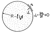
Figure 7.9.10 Configuration for an electrocardiogram, including voltages typically generated at body periphery by the heart. Here we simply represent the heart by a dipole source of current at the center of a conducting sphere, somewhat as depicted in Figs. 7.9.10 and 7.9.11. Relatively little current is induced in the limbs, so that potentials measured at the extremities roughly reflect the potentials on the surface of the equivalent sphere. Given that typical potential differences are on the order of millivolts, what current dipole moment can we attribute to the heart, and what are the typical current densities in its neighborhood?
With the heart represented by a current source of dipole moment ip d at the center of the spherical "torso," the electric potential at the origin approaches that for the dipole current source, (7.3.9).
Figure 7.9.11 Body and heart modeled by spherical conductor and dipole current. At the surface r = R, the spherical body is being surrounded by an insulator. Thus, again using Fig. 7.9.11, any normal conduction current must be accounted for by the accumulation of surface charge. Because the relaxation time is so short compared to the 1 s period typical of the heart, the current density associated with the buildup of surface charge is extremely small. As a result, the current distribution inside the sphere is as though the normal current density at r = R were zero.
Thus, the potential within the body is fully determined without regard for constraints from the surrounding region. The solution to Laplace's equation that satisfies these last two conditions is
Because the potential is continuous at r = R, the potential on the surface of the "torso" follows from evaluation of this expression at r = R.
Thus, given that the potential difference between
= 45 degrees and
= 135 degrees is 1 mV, that R = 25 cm, and that
= 0.2 S/m, it follows from (47) that the peak current dipole moment of the heart is 3.7 x 10⁻⁵ A - m.
Typical current densities can now be found using (46) to evaluate the electric field intensity. For example, the current density at the radius R/2 just above the dipole source is
Note that at the particular position selected the current density exceeds with some margin that to which the maintenance worker is subjected in the previous demonstration.
To begin to correlate the state and function of the heart with electrocardiograms, it is necessary to represent the heart by a current dipole that not only has a special temporal signature but rotates with time as well[1,2]. Unfortunately, much of the medical literature on the subject takes the analogy between electric dipoles (Sec.4.4) and current dipoles (Sec. 7.3) literally. The heart is described as an electric dipole[2], which it certainly is not. If it were, its fields would be shielded out by the surrounding conducting flesh.


