| | Conduction Constitutive Laws |
|---|
| 7.1.1 | In a metal such as copper, where each atom contributes
approximately one conduction electron, typical current densities are
the result of electrons moving at a surprisingly low velocity. To
estimate this velocity, assume that each atom contributes one
conduction electron and that the material is copper, where the
molecular weight Mo = 63.5 and the mass density is  = 8.9
x 103 kg/m3. Thus, the density of electrons is approximately
(Ao/Mo) = 8.9
x 103 kg/m3. Thus, the density of electrons is approximately
(Ao/Mo) , where Ao = 6.023 x 1026
molecules/kg-mole is Avogadro's number. Given , where Ao = 6.023 x 1026
molecules/kg-mole is Avogadro's number. Given  from Table 7.1.1,
what is the mobility of the electrons in copper? What electric field
intensity is required to drive a current density of l amp/cm2?
What is the electron velocity? from Table 7.1.1,
what is the mobility of the electrons in copper? What electric field
intensity is required to drive a current density of l amp/cm2?
What is the electron velocity?
|
| | Steady Ohmic Conduction |
|---|
| 7.2.1* | The circular disk of uniformly conducting material shown in Fig.
P7.2.1 has a dc voltage v applied to its surfaces at r = a and r
= b by
means of perfectly conducting electrodes. The other boundaries are
interfaces with free space. Show that the resistance
R = ln(a/b)/2  d. d.
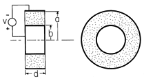 Figure P7.2.1
|
| 7.2.2 | In a spherical version of the resistor shown in Fig. P7.2.1, a
uniformly conducting material is connected to a voltage source v
through spherical perfectly conducting electrodes at r = a and r =
b. What is the resistance?
|
| 7.2.3* |
By replacing    , resistors are made to have the same
geometry as shown in Fig. P6.5.1. In general, the region between the
plane parallel perfectly conducting electrodes is filled by a material
of conductivity , resistors are made to have the same
geometry as shown in Fig. P6.5.1. In general, the region between the
plane parallel perfectly conducting electrodes is filled by a material
of conductivity  = =  (x). The boundaries of the
conductor that
interface with the surrounding free space have normals that are either
in the x or the z direction. (x). The boundaries of the
conductor that
interface with the surrounding free space have normals that are either
in the x or the z direction.
|
| 7.2.4 | A pair of uniform conductors form a resistor having the shape of
a circular cylindrical half-shell, as shown in Fig. P7.2.4. The
boundaries at r = a and r = b, and in planes parallel to the paper,
interface with free space. Show that for steady conduction, all
boundary conditions are satisfied by a simple piece-wise continuous
potential that is an exact solution to Laplace's equation. Determine
the resistance.
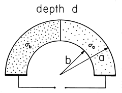 Figure P7.2.4
|
| 7.2.5* | The region between the planar electrodes of Fig. 7.2.4 is filled
with a material having conductivity  = =  o/(1 + y/a),
where o/(1 + y/a),
where  o and a are constants. The permittivity o and a are constants. The permittivity  is
uniform. is
uniform.
|
| 7.2.6 | The region between the planar electrodes of Fig. 7.2.4 is filled
with a uniformly conducting material having permittivity  = =  a/(1
+ y/a). a/(1
+ y/a).
| (a) | What is G?
|
| (b) | What is  u in the conductor? u in the conductor?
|
|
| 7.2.7* | A section of a spherical shell of conducting material with inner
radius b and outer radius a is shown in Fig. P7.2.7. Show
that if  = =  o (r/a)2, the conductance G =
6 o (r/a)2, the conductance G =
6 (1 - cos (1 - cos  /2 ) ab3 /2 ) ab3  o/(a3 - b3). o/(a3 - b3).
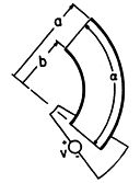 Figure P7.2.7
|
| 7.2.8 | In a cylindrical version of the geometry shown in Fig. P7.2.7,
the material between circular cylindrical outer and inner electrodes
of radii a and b, respectively, has conductivity  = =  o
(a/r). The boundaries parallel to the page interface free space and
are a distance d apart. Determine the conductance G. o
(a/r). The boundaries parallel to the page interface free space and
are a distance d apart. Determine the conductance G.
|
| | Distributed Current Sources and Associated Fields |
|---|
| 7.3.1* | An infinite half-space of uniformly conducting material in the
region y > 0 has an interface with free space in the plane y = 0.
There is a point current source of I amps located at (x, y, z) =
(0, h, 0) on the
y axis. Using an approach analogous to that used in Prob. 6.6.5, show
that the potential inside the conductor is
 Now that the potential of the interface is known, show that the
potential in the free space region outside the conductor, where y < 0,
is

|
| 7.3.2 | The half-space y > 0 is of uniform conductivity while the remaining
space is insulating. A uniform line current source of density Kl
(A/m) runs parallel to the plane y = 0 along the line x = 0,
y = h.
| (a) | Determine  in the conductor. in the conductor.
|
| (b) | In turn, what is  in the
insulating half-space? in the
insulating half-space?
|
|
| 7.3.3* | A two-dimensional dipole current source consists of uniform line
current sources  Kl have the spacing d. The
cross-sectional view is as shown in Fig. 7.3.4, with Kl have the spacing d. The
cross-sectional view is as shown in Fig. 7.3.4, with 
  . Show that the associated potential is . Show that the associated potential is
 in the limit Kl
   , d , d  0, Kl d
finite. 0, Kl d
finite.
|
| | Superposition and Uniqueness of Steady Conduction Solutions
|
|---|
| 7.4.1* | A material of uniform conductivity has a spherical insulating
cavity of radius b at its center. It is surrounded by segmented
electrodes that are driven by current sources in such a way that at
the spherical outer surface r = a, the radial current density is
Jr = - Jo cos  , where Jo is a given constant. , where Jo is a given constant.
| (a) | Show that inside the conducting material, the potential is

|
| (b) | Evaluated at r = b, this gives the potential on the
surface bounding
the insulating cavity. Show that the potential in the cavity is

|
|
| 7.4.2 | A uniformly conducting material has a spherical interface at r = a,
with a surrounding insulating material and a spherical boundary at r =
b (b < a), where the radial current density is Jr = Jo cos
 , essentially independent of time. , essentially independent of time.
| (a) | What is  in the conductor? in the conductor?
|
| (b) | What is  in the insulating region surrounding the
conductor? in the insulating region surrounding the
conductor?
|
|
| 7.4.3 | In a system that stretches to infinity in the  x and x and  z
directions, there is a layer of uniformly conducting material having
boundaries in the planes y = 0 and y = -a. The region y > 0
is free space, while a potential z
directions, there is a layer of uniformly conducting material having
boundaries in the planes y = 0 and y = -a. The region y > 0
is free space, while a potential  = V cos = V cos  x is imposed on
the boundary at y = -a. x is imposed on
the boundary at y = -a.
| (a) | Determine  in the conducting layer. in the conducting layer.
|
| (b) | What is  in the region y > 0? in the region y > 0?
|
|
| 7.4.4* | The uniformly conducting material shown in cross-section in Fig.
P7.4.4 extends to infinity in the  z directions and has the shape
of a 90-degree section from a circular cylindrical annulus. At z directions and has the shape
of a 90-degree section from a circular cylindrical annulus. At
 = 0 and = 0 and  = =  /2, it is in contact with grounded electrodes.
The boundary at r = a interfaces free space, while at r = b, an
electrode constrains the potential to be v. Show that the
potential in the conductor is /2, it is in contact with grounded electrodes.
The boundary at r = a interfaces free space, while at r = b, an
electrode constrains the potential to be v. Show that the
potential in the conductor is

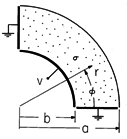 Figure P7.4.4
Figure P7.4.5
|
| 7.4.5 | The cross-section of a uniformly conducting material that extends
to infinity in the  z directions is shown in Fig. P7.4.5. The
boundaries at r = b, at z directions is shown in Fig. P7.4.5. The
boundaries at r = b, at  = 0, and at = 0, and at  = =  interface
insulating material. At r = a, voltage sources constrain interface
insulating material. At r = a, voltage sources constrain  =
-v/2 over the range 0 < =
-v/2 over the range 0 <  < <  /2, and /2, and  = v/2 over the
range = v/2 over the
range  /2 < /2 <  < <  . .
| (a) | Find an infinite set of solutions for  that satisfy the boundary conditions at the three insulating surfaces. that satisfy the boundary conditions at the three insulating surfaces.
|
| (b) | Determine  in the conductor. in the conductor.
|
|
| 7.4.6 | The system of Fig. P7.4.4 is altered so that there is an
electrode on the boundary at r = a. Determine the mutual conductance
between this electrode and the one at r = b.
|
| | Steady Currents in Piece-Wise Uniform Conductors |
|---|
| 7.5.1* | A sphere having uniform conductivity  b is surrounded by
material having the uniform conductivity b is surrounded by
material having the uniform conductivity  a. As shown in Fig.
P7.5.1, electrodes at "infinity" to the right and left impose a
uniform current density Jo at infinity. Steady conduction
prevails. Show that a. As shown in Fig.
P7.5.1, electrodes at "infinity" to the right and left impose a
uniform current density Jo at infinity. Steady conduction
prevails. Show that

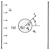 Figure P7.5.1
|
| 7.5.2 | Assume at the outset that the sphere of Prob. 7.5.1 is much more
highly conducting than its surroundings.
| (a) | As far as the fields
in region (a) are concerned, what is the boundary condition at r =
R?
|
| (b) | Determine the approximate potential in region (a) and
compare to the appropriate limiting potential from Prob. 7.5.1.
|
| (c) | Based on this
potential in region (a), determine the approximate potential in the
sphere and compare to the appropriate limit of  as found in Prob.
7.5.1. as found in Prob.
7.5.1.
|
| (d) | Now, assume that the sphere is much more insulating than its
surroundings. Repeat the steps of parts (a)-(c).
|
|
| 7.5.3* | A rectangular box having depth b, length l and width much
larger than b has an insulating bottom and metallic ends which serve
as electrodes. In Fig. P7.5.3a, the right electrode is extended upward
and then back over the box. The box is filled to a depth b with a
liquid having uniform conductivity. The region above is air. The
voltage source can be regarded as imposing a potential in the plane
z = -l between the left and top electrodes that is linear.
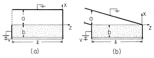 Figure P7.5.3
|
| 7.5.4 | The structure shown in Fig. P7.5.4 is infinite in the  z
directions. Each leg has the same uniform conductivity, and conduction
is stationary. The walls in the x and in the y planes are perfectly
conducting. z
directions. Each leg has the same uniform conductivity, and conduction
is stationary. The walls in the x and in the y planes are perfectly
conducting.
| (a) | Determine  , E, and J in the conductors. , E, and J in the conductors.
|
| (b) | What are  and E in the free space region? and E in the free space region?
|
| (c) | Sketch  and E in this region and in the conductors. and E in this region and in the conductors.
|
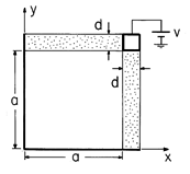 Figure P7.5.4
|
| 7.5.5 | The system shown in cross-section by Fig. P7.5.6a extends to
infinity in the  x and x and  z directions. The material of uniform
conductivity z directions. The material of uniform
conductivity  a to the right is bounded at y = 0 and y = a
by electrodes at zero potential. The material of uniform conductivity a to the right is bounded at y = 0 and y = a
by electrodes at zero potential. The material of uniform conductivity
 b to the left is bounded in these planes by electrodes each
at the potential v. The approach to finding the fields is similar to
that used in Example 6.6.3. b to the left is bounded in these planes by electrodes each
at the potential v. The approach to finding the fields is similar to
that used in Example 6.6.3.
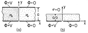 Figure P7.5.5
|
| | Conduction Analogs |
|---|
| 7.6.1* | In deducing (4) relating the capacitance of electrodes in an
insulating material to the conductance of electrodes having the same
shape in a conducting material, it is assumed that not only are the
ratios of all dimensions in one situation the same as in the other
(the systems are geometrically similar), but that the actual size of
the two physical situations is the same. Show that if the systems are
again geometrically similar but the length scale of the capacitor is
l while that of the conduction cell is l while that of the conduction cell is l , RC = ( , RC = ( /
/ )(l )(l /l /l ). ).
|
| | Charge Relaxation in Uniform Conductors |
|---|
| 7.7.1* | In the two-dimensional configuration of Prob. 4.1.4,
consider the field transient that results if the region within the
cylinder of rectangular cross-section is filled by a material having
uniform conductivity  and permittivity and permittivity  . .
|
| 7.7.2 | When t = 0, the only net charge in a material having uniform
 and and  is the line charge of Prob. 4.5.4. As a function
of time for t > 0, determine the is the line charge of Prob. 4.5.4. As a function
of time for t > 0, determine the
| (a) | line charge density,
|
| (b) | charge density elsewhere in the medium, and
|
| (c) | the potential  (x, y, z, t). (x, y, z, t).
|
|
| 7.7.3* | When t = 0, the charged particle of Example 7.7.2 has a charge
q = qo < -qc.
|
| 7.7.4 | Relative to the potential at infinity on a plane passing through
the equator of the particle in Example 7.7.2, what is the potential
of the particle when its charge reaches q = qc?
|
| | Electroquasistatic Conduction Laws for Inhomogeneous Materials
|
|---|
| 7.8.1* | Use an approach similar to that illustrated in this section to
show uniqueness of the solution to Poisson's equation for a given
initial distribution of  and a given potential and a given potential  = =
  on the surface S', and a given current density
-( on the surface S', and a given current density
-(   + +     / / t) t)  n = J n = J on S" where S' + S" encloses
the volume of interest V.
|
| | Charge Relaxation in Uniform and Piece-Wise Uniform Systems
|
|---|
| 7.9.1* | We return to the coaxial circular cylindrical electrode
configurations of Prob. 6.5.5. Now the material in region (2) of
each has not only a uniform permittivity  but a uniform
conductivity but a uniform
conductivity  as well. Given that V(t) = Re as well. Given that V(t) = Re  exp
(j exp
(j t), t),
| (a) | show that E in the first configuration of Fig. P6.5.5 is ir v/r ln(a/b),
|
| (b) | while in the second configuration,
 where Det = [
 ln(a/R)] + j ln(a/R)] + j [ [ o ln(R/b) + o ln(R/b) +  ln(a/R)].
|
| (c) | Show that in the first configuration a length l (into
the paper) is equivalent to a conductance G in parallel with a
capacitance C where
 while in the second, it is equivalent to the circuit of Fig. 7.9.5 with


|
|
| 7.9.2 | Interpret the configurations shown in Fig. P6.5.5 as spherical.
An outer spherically shaped electrode has inside radius a, while an
inner electrode positioned on the same center has radius b. Region
(1) is free space while (2) has uniform  and and  . .
| (a) | For V = Vo cos ( t), determine E in each region. t), determine E in each region.
|
| (b) | What are the elements in the equivalent
circuit for each?
|
|
| 7.9.3* | Show that the hemispherical electrode of Fig. 7.3.3 is equivalent
to a circuit having a conductance G = 2  a in parallel with a
capacitance C = 2 a in parallel with a
capacitance C = 2  a. a.
|
| 7.9.4 | The circular cylinder of Fig. P7.9.4a has  b and b and  b and is
surrounded by material having b and is
surrounded by material having  a and a and  a. The electric
field E(t)ix is applied at x = a. The electric
field E(t)ix is applied at x =   . .
| (a) | Find the potential in and around the cylinder and
the surface charge density that result from applying a step in field
to a system that initially is free of charge.
|
| (b) | Find these quantities
for the sinusoidal steady state response.
|
| (c) | Argue that these fields
are equally applicable to the description of the configuration shown
in Fig. P7.9.4b with the cylinder replaced by a half-cylinder on a
perfectly conducting ground plane. In
the limit where the exterior region is free space while the
half-cylinder is so conducting that its charge relaxation time is
short compared to times characterizing the applied field (1/ in
the sinusoidal steady state case), what are the approximate fields in
the exterior and in the interior regions? (See Prob. 7.9.5 for a
direct calculation of these approximate fields.) in
the sinusoidal steady state case), what are the approximate fields in
the exterior and in the interior regions? (See Prob. 7.9.5 for a
direct calculation of these approximate fields.)
|
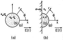 Figure P7.9.4
|
| 7.9.5* | The half-cylinder of Fig. P7.9.4b has a relaxation time that is
short compared to times characterizing the applied field E(t). The
surrounding region is free space ( a = 0). a = 0).
| (a) | Show that in the exterior region, the potential is
approximately

|
| (b) | In turn, show that the field inside the half-cylinder is
approximately

|
|
| 7.9.6 | An electric dipole having a z-directed moment p(t) is situated at
the origin and at the center of a spherical cavity of free space
having a radius a in a material having uniform  and and  .
When t < 0, p = 0 and there is no charge anywhere. The dipole
is a step
function of time, instantaneously assuming a moment po when t =
0. .
When t < 0, p = 0 and there is no charge anywhere. The dipole
is a step
function of time, instantaneously assuming a moment po when t =
0.
|
| 7.9.7* | A planar layer of semi-insulating material has thickness d,
uniform permittivity  , and uniform conductivity , and uniform conductivity  , as shown in
Fig. P7.9.7. From below it is bounded by contacting electrode
segments that impose the potential , as shown in
Fig. P7.9.7. From below it is bounded by contacting electrode
segments that impose the potential  = V cos = V cos  x. The
system extends to infinity in the x. The
system extends to infinity in the  x and x and  z directions. z directions.
| (a) | The potential has been applied for a long time. Show that at y = 0,  su = su =  o V o V  cos cos  x/cosh x/cosh  d. d.
|
| (b) | When t = 0, the applied potential is turned off. Show
that this unpaired surface charge density decays exponentially from
the initial value from part (a) with the time constant  = ( = ( o
tanh o
tanh  d + d +  )/ )/ . .
|
 Figure P7.9.7
|
| 7.9.8* | Region (b), where y < 0, has uniform permittivity  and
conductivity and
conductivity  , while region (a), where 0 < y, is free space.
Before t = 0 there are no charges. When t = 0, a point charge
Q is suddenly "turned on" at the location (x, y, z) = (0, h, 0). , while region (a), where 0 < y, is free space.
Before t = 0 there are no charges. When t = 0, a point charge
Q is suddenly "turned on" at the location (x, y, z) = (0, h, 0).
|
| 7.9.9* | The cross-section of a two-dimensional system is shown in Fig.
P7.9.9. The parallel plate capacitor to the left of the plane x = 0
extends to x = - , with the lower electrode at potential v(t) and
the upper one grounded. This upper electrode extends to the right to
the plane x = b, where it is bent downward to y = 0 and inward to the
plane x = 0 along the surface y = 0. Region (a) is free space while
region (b) to the left of the plane x = 0 has uniform permittivity , with the lower electrode at potential v(t) and
the upper one grounded. This upper electrode extends to the right to
the plane x = b, where it is bent downward to y = 0 and inward to the
plane x = 0 along the surface y = 0. Region (a) is free space while
region (b) to the left of the plane x = 0 has uniform permittivity  and conductivity
  . The applied voltage v(t) is a step
function of magnitude Vo. . The applied voltage v(t) is a step
function of magnitude Vo.
 Figure P7.9.9
|
 = 8.9
x 103 kg/m3. Thus, the density of electrons is approximately
(Ao/Mo)
 , where Ao = 6.023 x 1026
molecules/kg-mole is Avogadro's number. Given
  from Table 7.1.1,
what is the mobility of the electrons in copper? What electric field
intensity is required to drive a current density of l amp/cm2?
What is the electron velocity?

 d.
d.


 , resistors are made to have the same
geometry as shown in Fig. P6.5.1. In general, the region between the
plane parallel perfectly conducting electrodes is filled by a material
of conductivity
  =
=  (x). The boundaries of the
conductor that
interface with the surrounding free space have normals that are either
in the x or the z direction.
 a and
a and  b of width a and b,
respectively, as shown in Fig. P6.5.1a, show that the conductance G
= c(
 b b +
b b +  a a)/d.
 =
=  a(1 + x/l), show that G = 3
 a
cl/2d.

 =
=  o/(1 + y/a),
where
  o and a are constants. The permittivity
  is
uniform.
 o/d(1 + d/2a).
 u =
u =  Gv/A
Gv/A o a.
o a.
 =
=  a/(1
+ y/a).
 u in the conductor?
 =
=  o (r/a)2, the conductance G =
6
 (1 - cos
  /2 ) ab3
  o/(a3 - b3).

 =
=  o
(a/r). The boundaries parallel to the page interface free space and
are a distance d apart. Determine the conductance G.


 in the conductor.
 in the
insulating half-space?
 Kl have the spacing d. The
cross-sectional view is as shown in Fig. 7.3.4, with

 . Show that the associated potential is


 , d
, d  0, Kl d
finite.
 , where Jo is a given constant.


 , essentially independent of time.
 in the conductor?
 in the insulating region surrounding the
conductor?
 x and
x and  z
directions, there is a layer of uniformly conducting material having
boundaries in the planes y = 0 and y = -a. The region y > 0
is free space, while a potential
  = V cos
  x is imposed on
the boundary at y = -a.
 in the conducting layer.
 in the region y > 0?
 z directions and has the shape
of a 90-degree section from a circular cylindrical annulus. At
 = 0 and
  =
=  /2, it is in contact with grounded electrodes.
The boundary at r = a interfaces free space, while at r = b, an
electrode constrains the potential to be v. Show that the
potential in the conductor is


 z directions is shown in Fig. P7.4.5. The
boundaries at r = b, at
  = 0, and at
  =
=  interface
insulating material. At r = a, voltage sources constrain
  =
-v/2 over the range 0 <
  <
<  /2, and
  = v/2 over the
range
  /2 <
/2 <  <
<  .
.
 that satisfy the boundary conditions at the three insulating surfaces.
 in the conductor.
 b is surrounded by
material having the uniform conductivity
  a. As shown in Fig.
P7.5.1, electrodes at "infinity" to the right and left impose a
uniform current density Jo at infinity. Steady conduction
prevails. Show that


 as found in Prob.
7.5.1.
 = -vz/l.
 = v(z/l)(x - a)/a.
 u and
u and  u?
u?
 in the conductor is unaltered but
in the region between the conductor and the slanted plate,
  =
v[(z/l) + (x/a)].

 z
directions. Each leg has the same uniform conductivity, and conduction
is stationary. The walls in the x and in the y planes are perfectly
conducting.
 , E, and J in the conductors.
 and E in the free space region?
 and E in this region and in the conductors.

 x and
x and  z directions. The material of uniform
conductivity
  a to the right is bounded at y = 0 and y = a
by electrodes at zero potential. The material of uniform conductivity
 b to the left is bounded in these planes by electrodes each
at the potential v. The approach to finding the fields is similar to
that used in Example 6.6.3.
 a as x
 and
and  b as
x
  -
- ?
?


 .
.
 a to
a to  b in the plane x = 0?
 throughout the region between the electrodes.
 b
b 
 a and
a and  b =
b =
 a, sketch
  and E.
(A numerical evaluation of the expressions for
 is not required.)

 while that of the conduction cell is l
 , RC = (
 /
/ )(l
)(l /l
/l ).
).
 and permittivity
  .
.
 o
o 
 and
and  o a given constant, show that
  u
(x, y, t = 0) is given by (c) of Prob. 4.1.4.
 is given by (c) of Prob. 4.1.4 multiplied by
exp (-t/
 ), where
  =
=  /
/ .
.
 ).
).
 and
and  is the line charge of Prob. 4.5.4. As a function
of time for t > 0, determine the
 (x, y, z, t).

 /
/ q.
q.
 1) where
  1 =
1 =  /
/
 .
.
 and a given potential
  =
=

 on the surface S', and a given current density
-(

 +
+ 


 /
/ t)
t)  n = J
n = J on S" where S' + S" encloses
the volume of interest V.
 but a uniform
conductivity
  as well. Given that V(t) = Re
  exp
(j
 t),
t),

 ln(a/R)] + j
 [
[ o ln(R/b) +
  ln(a/R)].


 and
and  .
.
 t), determine E in each region.

 a in parallel with a
capacitance C = 2
 a.
a.
 b and
b and  b and is
surrounded by material having
  a and
a and  a. The electric
field E(t)ix is applied at x =
 .
.
 in
the sinusoidal steady state case), what are the approximate fields in
the exterior and in the interior regions? (See Prob. 7.9.5 for a
direct calculation of these approximate fields.)

 a = 0).


 and
and  .
When t < 0, p = 0 and there is no charge anywhere. The dipole
is a step
function of time, instantaneously assuming a moment po when t =
0.
 inside and outside the cavity?
 ?
?
 (r,
(r,  , t).
, t).
 , and uniform conductivity
  , as shown in
Fig. P7.9.7. From below it is bounded by contacting electrode
segments that impose the potential
  = V cos
  x. The
system extends to infinity in the
  x and
x and  z directions.
 su =
su =  o V
o V  cos
cos  x/cosh
  d.
d.
 = (
= ( o
tanh
  d +
d +  )/
)/ .
.

 and
conductivity
  , while region (a), where 0 < y, is free space.
Before t = 0 there are no charges. When t = 0, a point charge
Q is suddenly "turned on" at the location (x, y, z) = (0, h, 0).


 Q[(
Q[( /
/ o ) - 1]/[(
 /
/ o ) + 1] and qa
 2Q/[(
2Q/[( /
/ o ) + 1].

 , qb
, qb  Q
and the field in region (b) goes to zero.


 = (
= ( o +
o +  )/
)/ .
.
 , with the lower electrode at potential v(t) and
the upper one grounded. This upper electrode extends to the right to
the plane x = b, where it is bent downward to y = 0 and inward to the
plane x = 0 along the surface y = 0. Region (a) is free space while
region (b) to the left of the plane x = 0 has uniform permittivity
  and conductivity
  . The applied voltage v(t) is a step
function of magnitude Vo.
 b, what is the potential in region (a)?
 is to be found for t > 0. Example 6.6.3
illustrates the
approach that can be used. Show that in the limit t
 ,
,  becomes the result of part (a).
 =
=  o, sketch the
evolution of the field from the time just
after the voltage is applied to the long-time limit of part (a).


