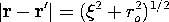
Once the vector potential has been determined from the superposition integral of Sec. 8.1, the magnetic flux density follows from an evaluation of curl A. However, in certain field evaluations, it is best to have a superposition integral for the field itself. For example, in numerical calculations, numerical derivatives should be avoided.
The field superposition integral follows by operating on the vector potential as given by (8.1.8) before the integration has been carried out.
The integration is with respect to the source coordinates denoted by r', while the curl operation involves taking derivatives with respect to the observer coordinates r. Thus, the curl operation can be carried out before the integral is completed, and (1) becomes
The curl operation required to evaluate the integrand in this expression can be carried out without regard for the particular dependence of the current density because the derivatives are with respect to r, not r'. To make this evaluation, observe that the curl operates on the product of the vector J and the scalar
= |r - r'|-1, and that operation obeys the vector identity
Because J is independent of r, the first term on the right is zero. Thus, (2) becomes
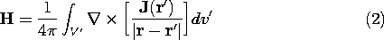
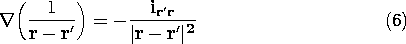
To evaluate the gradient in this expression, consider the special case when r' is at the origin in a spherical coordinate system, as shown in Fig. 8.2.1. Then
where ir is the unit vector directed from the source coordinate at the origin to the observer coordinate at (r,
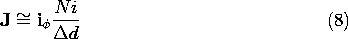
,
).
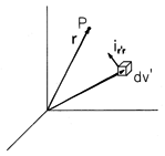
Figure 8.2.1 Spherical coordinate system with r' located at origin. Figure 8.2.2 Source coordinate r' and observer coordinate r showing unit vector ir' r directed from r' to r. We now move the source coordinate from the origin to the arbitrary location r'. Then the distance r in (5) is replaced by the distance |r - r' |. To replace the unit vector ir, the source-observer unit vector ir' r is defined as being directed from an arbitrary source coordinate to the observer coordinate P. In terms of this source-observer unit vector, illustrated in Fig. 8.2.2, (5) becomes
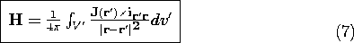
Substitution of this expression into (4) gives the Biot-Savart Law for the magnetic field intensity.
In evaluating the integrand, the cross-product is evaluated at the source coordinate r'. The integrand represents the contribution of the current density at r' to the field at r. The following examples illustrate the Biot-Savart law.
Example 8.2.1. On Axis Field of Circular Cylindrical Solenoid
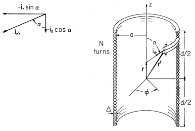
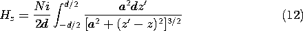
The cross-section of an N-turn solenoid of axial length d and radius a is shown in Fig. 8.2.3. There are many turns, so the current i passing through each is essentially
Figure 8.2.3 A solenoid consists of N turns uniformly wound over a length d, each turn carrying a current i. The field is calculated along the z axis, so the observer coordinate is at r on the z axis.
In cylindrical coordinates, the source coordinate incremental volume element is dv' = r' d
, the current density is essentially the total number of turns multiplied by the current per turn and divided by the area through which the current flows.
The superposition integral, (7), is carried out first on r'. This extends from r' = a to r' = a +
a, the source-observer distance and direction remain essentially constant over this interval, and so the integration amounts to a multiplication by
In terms of the angle
shown in Fig. 8.2.3 and its inset, the source-observer unit vector is
so that
The integrand in (9) is
.
With the substitution z" = z' - z, it follows that
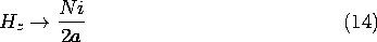
In the limit where d/2a
Thus, a 100-turn circular loop having a radius a = 5 cm (that is large compared to its axial length d) and carrying a current of i = 1 A would have a field intensity of 1000 A/m at its center. The flux density measured by a magnetometer would then be B_z =
o H_z = 4
Further implications of this finding are discussed in the following demonstration.
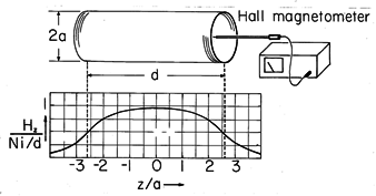
Demonstration 8.2.1. Fields of a Circular Cylindrical Solenoid
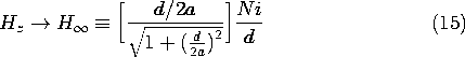
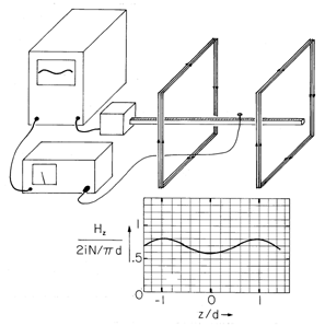
The solenoid shown in Fig. 8.2.4 has N = 141 turns, an axial length d = 70.5 cm, and a radius a = 13.6 cm. A Hall-type magnetometer measures the magnitude and direction of H in and around the coil. The on-axis distribution of H_z predicted by (13) for the experimental length-to-diameter ratio d/2a = 2.58 is shown in Fig. 8.2.4. With i = 1 amp, the flux density at the center approaches 2.5 gauss. The accuracy with which theory and experiment agree is likely to be limited only by such matters as the care with which the probe can be mounted and the calibration of the magnetometer. Care must also be taken that there are no magnetizable materials, such as iron, in the vicinity of the coil. To avoid contributions from the earth's magnetic field (which is on the order of a gauss), ac fields should be used. If ac is used, there should be no large conducting objects near by in which eddy currents might be induced. (Magnetization and eddy currents, respectively, are taken up in the next two chapters.)
Figure 8.2.4 Experiment for documenting the axial H predicted in Example 8.2.1. Profile of normalized Hz is for d/2a = 2.58. The infinitely long solenoid can be regarded as the analog for MQS systems of the "plane parallel plate capacitor." Just as the capacitor can be constructed to create a uniform electric field between the plates with zero field outside the region bounded by the plates, so too the long solenoid gives rise to a uniform magnetic field throughout the interior region and an exterior field that is zero. This can be seen by probing the field not only as a function of axial position but of radius as well. For the finite length solenoid, the on-axis interior field designated by H_
in Fig. 8.2.4 is given by (13) for locations on the z axis where d/2
z.
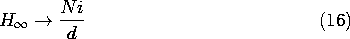
In the limit where the solenoid is also very long compared to its radius, where d/2a
Probing of the field shows the field maintains the value and direction of (16) over the interior cross-section as well. It also shows that the magnetic field intensity just outside the windings at an axial location that is several radii a from the coil ends is relatively small.
Continuity of magnetic flux requires that the total flux passing through the solenoid in the z direction must be returned in the -z direction outside the solenoid. How, then, can the exterior field of a long solenoid be negligible compared to that inside? The outside flux returns in the -z direction through a much larger exterior area than the area
Stick Model for Computing Fields of Electromagnet
The Biot-Savart superposition integral can be completed analytically for relatively few configurations. Nevertheless, its evaluation amounts to no more than a summation of the field contributions from each of the current elements. Thus, on the computer, its evaluation is a straightforward matter.
Many practical current distributions are, or can be approximated by, connected straight-line current segments, or current "sticks." We will now use the Biot-Savart law to find the field at an arbitrary observer position r associated with a current stick having an arbitrary location. The result is a practical resource, because a numerical summation over differential volume current elements can then be replaced by one over the sticks.
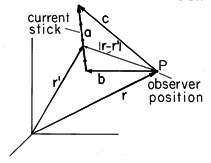
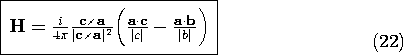
Figure 8.2.5 A line current i is uniformly distributed over the length of the vector a originating at r + b and terminating at r + c. The resulting magnetic field intensity is determined at the observer position r. The current stick, shown in Fig. 8.2.5, is represented by a vector a. Thus, the current is uniformly distributed between the base of this vector at r + b and the tip of the vector at r + c. The source coordinate r' is located along the current stick. The objective in the following paragraphs is to carry out an integration over the length of the current stick and obtain an expression for H (r). Because the current stick does not represent a solenoidal current density at its ends, the field derived is of physical significance only if used in conjunction with other current sticks that together represent a continuous current distribution.
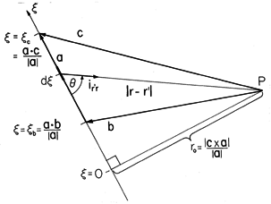
Figure 8.2.6 View of current element from Fig. 8.2.5 in plane containing b and c, and hence a. The detailed view of the current stick, Fig. 8.2.6, shows the source coordinate
denoting the position along the stick. The origin of this coordinate is at the point on a line through the stick that is closest to the observer coordinate.
The projection of b onto a vector a is
b /|a|. Thus, the current stick begins at this distance from
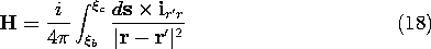
The cross-product c x a/|a| is perpendicular to the plane of Fig. 8.2.6 and equal in magnitude to the projection of c onto a vector that is perpendicular to a and in the plane of Fig. 8.2.6. Thus, the shortest distance between the observer position and the axis of the current stick is r_o = |c x a|/|a|. It follows from this fact and the definition of the cross-product that
where ds is the differential along the line current and
Integration of the Biot-Savart law, (7), is first performed over the cross-section of the stick. The cross-sectional dimensions are small, so during this integration, the integrand remains essentially constant. Thus, the current density is replaced by the total current and the integral reduced to one on the axial coordinate
In view of (17), this integral is expressed in terms of the source coordinate integration variable
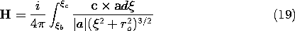
This integral is carried out to obtain
In evaluating this expression at the integration endpoints, note that by definition,
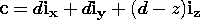
so that (20) becomes an expression for the field intensity at the observer location expressed in terms of vectors a , b, and c that serve to define the relative location of the current stick.
The following illustrates how this expression can be used repetitively to determine the field induced by currents represented in a piece-wise fashion by current sticks. Expressed in Cartesian coordinates, the vectors are a convenient way to specify the sticks making up a complex winding. On the computer, the evaluation of (22) is then conveniently carried out by a subroutine that is used many times.
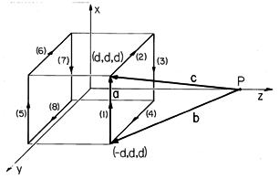
Example 8.2.2. Axial Field of a Pair of Square Coils
Shown in Fig. 8.2.7 is a pair of coils, each having N turns carrying a current i in such a direction that the fields induced by each coil reinforce along the z axis. The four linear sections of the two coils comprise the sides of a cube, centered at the origin and with dimensions 2d.
Figure 8.2.7 A pair of square N-turn coils produce a field at P on the z axis that is the superposition of the fields Hz due to the eight linear elements comprising the coils. The coils are centered on the z axis.
We confine ourselves to finding H along the z axis where, by symmetry, it has only a z component. Thus, for an observer at (0, 0, z), the vectors specifying element (1) of the right-hand coil in Fig. 8.2.7 are
Evaluation of the z component of (22) then gives the part of H_z due to element (1). Because of the axial symmetry, the field induced by elements (2), (3), and (4) in the same coil are the same as already found for element (1). The field induced by element (5) in the second coil is similarly found starting from vectors that are the same as in (23), except that d
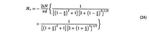
-d in the z components of b and c. Here too, the other three elements each contribute the same field as already found. Thus, the axial field intensity, the sum of the contributions from the individual coils, is
This distribution is plotted on the inset to Fig. 8.2.8. Because the fields induced by the separate coils reinforce, the pair can be used to produce a relatively uniform field in the midregion.
Figure 8.2.8 Demonstration of axial field generated by pair of square coils having spacing equal to the side lengths.
In the experiment of Fig. 8.2.8, the axial field is probed by means of a Hall magnetometer. The output is connected to the vertical trace of a high persistence scope. The probe is mounted on a carriage that is attached to a potentiometer in such a way that there is an output voltage proportional to the horizontal position of the probe. This is used to control the horizontal scope deflection. The result is a trace that follows the predicted contour. The plot is shown in terms of normalized coordinates that can be used to compare theory to experiment using any size of coils and any level of current.