There are physical situations in which the current distribution is not prespecified but is given by some equivalent information. Thus, for example, a perfectly conducting body in a time-varying magnetic field supports surface currents that shield the H field from the interior of the body. The effect of the conductor on the magnetic field is reminiscent of the EQS situations of Sec. 4.6, where charges distributed themselves on the surface of a conductor in such a way as to shield the electric field out of the material.
We found in Chap. 7 that the EQS model of a perfect conductor described the low-frequency response of systems in the sinusoidal steady state, or the long-time response to a step function drive. We will find in Chap. 10 that the MQS model of a perfect conductor represents the high-frequency sinusoidal steady state response or the short-time response to a step drive.
Usually, we use the model of perfect conductivity to describe bodies of high but finite conductivity. The value of conductivity which justifies use of the perfect conductor model depends on the frequency (or time scale in the case of a transient) as well as the geometry and size, as will be seen in Chap. 10. When the material is cooled to the point where it becomes superconducting, a type I superconductor (for example lead) expels any mangetic field that might have originally been within its interior, while showing zero resistance to currrent flow. Thus, even for dc, the material acts on the magnetic field like a perfect conductor. However, type I materials also act to exclude the flux from the material, so they should be regarded as perfect conductors in which flux cannot be trapped. The newer "high temperature ceramic superconductors," such as Y1Ba2Cu3O7, show a type II regime. In this class of superconductors, there can be trapped flux if the material is cooled in a dc field. "High temperature superconductors" are those that show a zero resistance at temperatures above that of liquid nitrogen, 77 degrees Kelvin.
As for EQS systems, Faraday's continuity condition, (1.6.12),
requires that the tangential E be continuous at a boundary between
free space and a conductor. By definition, a stationary perfect
conductor cannot have an electric field in its interior. Thus, in MQS
as well as EQS systems, there can be no tangential E at the
surface of a perfect conductor. But the primary laws determining
H in the free space region, Ampère's law with J = 0 and
the flux continuity condition, do not involve the electric field.
Rather, they involve the magnetic field, or perhaps the vector or
scalar potential. Thus, it is desirable to also state the boundary
condition in terms of H or  .
.
Boundary Conditions and Evaluation of Induced Surface Current Density
To identify the boundary condition on the magnetic field at the surface of a perfect conductor, observe first that the magnetic flux continuity condition requires that if there is a time-varying flux density n
 o H normal to the surface on the free
space side, then there must be the same flux density on the conductor
side. But this means that there is then a time-varying flux density
in the volume of the perfect conductor. Faraday's law, in turn,
requires that there be a curl of E in the conductor. For this to
be true, E must be finite there, a contradiction of our definition
of the perfect conductor. We conclude that there can be no normal
component of a time-varying magnetic flux density at a perfectly
conducting surface.

Correspondingly, if the H field is the gradient of the scalar
potential  , we find that

on the surface of a perfect conductor. This should be contrasted
with the boundary condition for an EQS potential  which must be
constant on the surface of a perfect conductor.
This boundary condition can be used to determine the magnetic field
distribution in the neighborhood of a perfect conductor. Once this
has been done, Ampère's continuity condition, (1.4.16), can be used
to find the surface current density that has been induced by the
time-varying magnetic field. With n directed from the perfect
conductor into the region of free space,

Because there is no time-varying magnetic field in the conductor, only the tangential field intensity on the free space side of the surface is required in this evaluation of the surface current density.
Example 8.4.1. Perfectly Conducting Cylinder in a Uniform Magnetic Field
A perfectly conducting cylinder having radius R and extending to z =

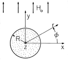
is immersed in a uniform time-varying magnetic field. This field is y directed and has intensity Ho at infinity, as shown in Fig. 8.4.1. What is the distribution of H in the neighborhood of the cylinder?
Figure 8.4.1 Perfectly conducting circular cylinder of radius R in a magnetic field that is y directed and of magnitude Ho far from the cylinder.
In the free space region around the cylinder, there is no current density. Thus, the field can be written as the gradient of a scalar potential (in two dimensions)
The far field has the potential
The condition
/
n = 0 on the surface of the cylinder suggests that the boundary condition at r = R can be satisfied by adding to (5) a dipole solution proportional to sin
/r. By inspection,
has the property
/
r = 0 at r = R. The magnetic field follows from (6) by taking its negative gradient
The current density induced on the surface of the cylinder, and responsible for generating the magnetic field that excludes the field from the interior of the cylinder, is found by evaluating (3) at r = R.
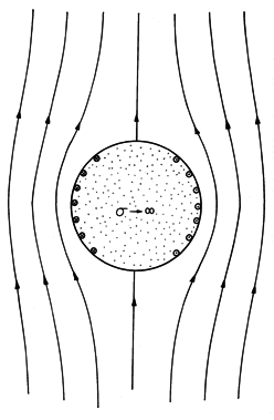
The field intensity of (7) and this surface current density are shown in Fig. 8.4.2. Note that the polarity of K is such that it gives rise to a magnetic dipole field that tends to buck out the imposed field. Comparison of (7) and the field of a two-dimensional dipole, (8.1.21), shows that the induced moment is id = 2
Ho R2.
Figure 8.4.2 Lines of magnetic field intensity for perfectly conducting cylinder in transverse magnetic field. There is an analogy to steady conduction (H
J) in the neighborhood of an insulating rod immersed in a conductor carrying a uniform current density. In Demonstration 7.5.2, an electric dipole field also bucked out an imposed uniform field (J) in such a way that there was no normal field on the surface of a cylinder.
Voltage at the Terminals of a Perfectly Conducting Coil
Faraday's law was the underlying reason for the vanishing of the flux density normal to a perfect conductor. By stating this boundary condition in terms of the magnetic field alone, we have been able to formulate the magnetic field of perfect conductors without explicitly solving for the distribution of electric field intensity. It would seem that for the determination of the voltage induced by a time-varying magnetic field at the terminals of the coil, knowledge of the E field would be necessary. In fact, as we now take care to define the circumstances required to make the terminal voltage of a coil a well-defined variable, we shall see that we can put off the detailed determination of E for Chap. 10.
The EMF at point (a) relative to that at point (b) was defined in
Sec. 1.6 as the line integral of E  ds from (a) to
(b). In Sec.
4.1, where the electric field was irrotational, this integral was then
defined as the voltage at point (a) relative to (b). We shall
continue to use this terminology, which is consistent with that used
in circuit theory.
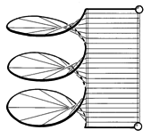
If the voltage is to be a well-defined quantity, independent of the layout of the connecting wires, the terminals of the coil shown in Fig. 8.4.3 must be in a region where the magnetic induction is negligible compared to that in other regions and where, as a result, the electric field is irrotational. To determine the voltage, the integral form of Faraday's law, (1.6.1), is applied to the closed line integral C shown in Fig. 8.4.3.

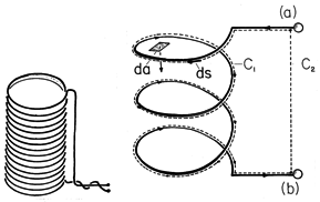
The contour goes from the terminal at (a) to that at (b) along the coil wire and closes through a path outside the coil. However, we know that E is zero along the perfectly conducting wire. Hence, the entire contribution to the line integral comes from the short path between the terminals. Thus, the left side of (9) reduces to

It follows from Faraday's law, (9), that the terminal voltage is

where  is the flux linkage


