| | The Vector Potential and the Vector Poisson Equation |
|---|
| 8.1.1 | A solenoid has radius a, length d, and turns N, as shown in Fig.
8.2.3. The length d is much greater than a, so it can be
regarded as being infinite. It is driven by a current i.
| (a) | Show that Ampère's differential law and the magnetic flux
continuity law [(8.0.1) and (8.0.2)], as well as the associated
continuity conditions [(8.0.3) and (8.0.4)], are satisfied by an
interior magnetic field intensity that is uniform and an exterior one
that is zero.
|
| (b) | What is the interior field?
|
| (c) | A is continuous at r = a because otherwise the
H field would have a singularity. Determine A.
|
|
| 8.1.2* | A two-dimensional magnetic quadrupole is composed of four line
currents of magnitudes i, two in the positive z direction at x = 0,
y =  d/2 and two in the negative z direction at x = d/2 and two in the negative z direction at x =  d/2, y
= 0. (With the line charges representing line currents, the
cross-section is the same as shown in Fig. P4.4.3.)
Show that in the limit where r d/2, y
= 0. (With the line charges representing line currents, the
cross-section is the same as shown in Fig. P4.4.3.)
Show that in the limit where r  d, Az = - ( d, Az = - ( o
id2/4 o
id2/4 )(r-2) cos 2 )(r-2) cos 2 . (Note that distances must be
approximated accurately to order d2.) . (Note that distances must be
approximated accurately to order d2.)
|
| 8.1.3 | A two-dimensional coil, shown in cross-section in Fig. P8.1.3, is
composed of N turns of length l in the z direction that is much
greater than the width w or spacing d. The thickness of the windings
in the y direction is much less than w and d. Each turn carries the
current i. Determine A.
 Figure P8.1.3
|
| | The Biot-Savart Superposition Integral |
|---|
| 8.2.1* | The washer-shaped coil shown in Fig. P8.2.1 has a thickness  that is much less than the inner radius b and outer
radius a. It supports a current density J = Jo i
 .
Show that along the z axis, .
Show that along the z axis,

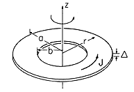 Figure P8.2.1
|
| 8.2.2* | A coil is wound so that the wire forms a spherical shell of
radius R with the wire essentially running in the  direction.
With the wire driven by a current source, the resulting current
distribution is a surface current at r = R having the density
K = Ko sin direction.
With the wire driven by a current source, the resulting current
distribution is a surface current at r = R having the density
K = Ko sin  i i , where Ko is a given constant.
There are no other currents. Show that at the center of the
coil, H = (2Ko/3)iz. , where Ko is a given constant.
There are no other currents. Show that at the center of the
coil, H = (2Ko/3)iz.
|
| 8.2.3 | In the configuration of Prob. 8.2.2, the surface current density
is uniformly distributed, so that K = Ko i , where
Ko is again a constant. Find H at the center of the coil. , where
Ko is again a constant. Find H at the center of the coil.
|
| 8.2.4 | Within a spherical region of radius R, the current density is
J = Jo i , where Jo is a given constant. Outside
this region is free space and no other sources of H. Determine
H at the origin. , where Jo is a given constant. Outside
this region is free space and no other sources of H. Determine
H at the origin.
|
| 8.2.5* | A current i circulates around a loop having the shape of an
equilateral triangle having sides of length d, as shown in Fig.
P8.2.5. The loop is in the z = 0 plane. Show that along the z
axis,

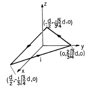 Figure P8.2.5
|
| 8.2.6 | For the two-dimensional coil of Prob. 8.1.3, use the Biot-Savart
superposition integral to find H along the x axis.
|
| 8.2.7* | Show that A induced at point P by the current stick of Figs.
8.2.5 and 8.2.6 is

|
| | The Scalar Magnetic Potential |
|---|
| 8.3.1 | Evaluate the H field on the axis of a circular loop of radius R
carrying a current i. Show that your result is consistent with the
result of Example 8.3.2 at distances from the loop much greater than
R.
|
| 8.3.2 | Determine  for two infinitely long parallel thin wires carrying
currents i in opposite directions parallel to the z axis of a
Cartesian coordinate system and located along x = for two infinitely long parallel thin wires carrying
currents i in opposite directions parallel to the z axis of a
Cartesian coordinate system and located along x =  a. Show that
the lines a. Show that
the lines  = const in the x - y plane are circles. = const in the x - y plane are circles.
|
| 8.3.3 | Find the scalar potential on the axis of a stack of circular
loops (a coil) of N turns and length l using 8.3.12 for an
individual turn, integrating over all the turns. Find H on the
axis.
|
| | Magnetoquasistatic Fields in the Presence of Perfect Conductors
|
|---|
| 8.4.1* | A current loop of radius R is at the center of a conducting
spherical shell having radius b. Assume that R  b and
that i(t) is so rapidly varying that the shell can be taken as
perfectly conducting. Show that in spherical coordinates, where R b and
that i(t) is so rapidly varying that the shell can be taken as
perfectly conducting. Show that in spherical coordinates, where R
 r < b r < b

|
| 8.4.2 | The two-dimensional magnetic dipole of Example 8.1.2 is at the
center of a conducting shell having radius a  d. The current
i(t) is so rapidly varying that the shell can be regarded as
perfectly conducting. What are d. The current
i(t) is so rapidly varying that the shell can be regarded as
perfectly conducting. What are  and H in the region d and H in the region d  r < a?
|
| 8.4.3* | The cross-section of a two-dimensional system is shown in Fig.
P8.4.3. A magnetic flux per unit length s o Ho is trapped
between perfectly conducting plane parallel plates that extend to
infinity to the left and right. At the origin on the lower plate is a
perfectly conducting half-cylinder of radius R. o Ho is trapped
between perfectly conducting plane parallel plates that extend to
infinity to the left and right. At the origin on the lower plate is a
perfectly conducting half-cylinder of radius R.
| (a) | Show that if s  R, then R, then

|
| (b) | Show that a plot of H would appear as in the left half
of Fig. 8.4.2 turned on its side.
|
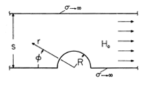 Figure P8.4.3
|
| 8.4.4 | In a three-dimensional version of that shown in Fig. P8.4.3, a
perfectly conducting hemispherical bump of radius s  R is attached
to the lower of two perfectly conducting plane parallel plates. The
hemisphere is centered at the origin of a spherical coordinate system
such as in Fig. P8.4.3, with R is attached
to the lower of two perfectly conducting plane parallel plates. The
hemisphere is centered at the origin of a spherical coordinate system
such as in Fig. P8.4.3, with    . The magnetic field
intensity is uniform far from the hemisphere. Determine . The magnetic field
intensity is uniform far from the hemisphere. Determine  and
H. and
H.
|
| 8.4.5* | Running from z = - to z = + to z = + at (x, y) = (0, -h) is
a wire. The wire is parallel to a perfectly conducting plane at y = 0.
When t = 0, a current step i = I u-1(t) is applied in the +z
direction to the wire. at (x, y) = (0, -h) is
a wire. The wire is parallel to a perfectly conducting plane at y = 0.
When t = 0, a current step i = I u-1(t) is applied in the +z
direction to the wire.
| (a) | Show that in the region y < 0,

|
| (b) | Show that the surface current density at y = 0 is
Kz = - ih/ (x2 + h2). (x2 + h2).
|
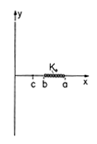 Figure P8.4.6
|
| 8.4.6 | The cross-section of a system that extends to infinity in the
 z directions is shown in Fig. P8.4.6. Surrounded by free space,
a sheet of current has the surface current density Ko iz
uniformly distributed between x = b and x = a. The plane x = 0
is perfectly conducting. z directions is shown in Fig. P8.4.6. Surrounded by free space,
a sheet of current has the surface current density Ko iz
uniformly distributed between x = b and x = a. The plane x = 0
is perfectly conducting.
| (a) | Determine  in the region 0 < x. in the region 0 < x.
|
| (b) | Find K in the plane x = 0.
|
|
| | Piece-Wise Magnetic Fields |
|---|
| 8.5.1* | The cross-section of a cylindrical winding is shown in Fig.
P8.5.1. As projected onto the y = 0 plane, the number of turns per unit
length is constant and equal to N/2R. The cylinder can be modeled as
infinitely long in the axial direction.
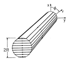 Figure P8.5.1
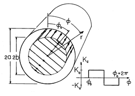 Figure P8.5.2
|
| 8.5.2 | The cross-section of a rotor, coaxial with a perfectly conducting
"magnetic shield," is shown in Fig. P8.5.2. Windings consisting of N
turns per unit peripheral length are distributed uniformly at r = b so
that at a given instant in time, the surface current distribution is as
shown. At r = a, there is the inner surface of a perfect conductor. The
system is very long in the z direction.
| (a) | What are the continuity
conditions on  at r = b and the boundary condition at r = a? at r = b and the boundary condition at r = a?
|
| (b) | Find  , and hence H, in regions (a) and (b) outside
and inside the winding, respectively. , and hence H, in regions (a) and (b) outside
and inside the winding, respectively.
|
| (c) | With the understanding that the rotor is
wound using one wire, so that each turn is in series with the next and
a wire carrying the current in the +z direction at  returns the
current in the -z direction at - returns the
current in the -z direction at - , what is the inductance of the
rotor coil? Why is it independent of the rotor position , what is the inductance of the
rotor coil? Why is it independent of the rotor position  o? o?
|
|
| | Vector Potential |
|---|
| 8.6.1* | In Example 1.4.1, the magnetic field intensity is determined to
be that given by (1.4.7). Define Az to be zero at the origin.
| (a) | Show that if H is to be finite in the neighborhood
of r = R, Az must be continuous there. is to be finite in the neighborhood
of r = R, Az must be continuous there.
|
| (b) | Show that A is given by

|
| (c) | The loop designated by C' in Fig. 1.4.2 has a
length l in the z direction, an inner leg at r = 0,
and an outer leg at r = a > R. Use A
to show that the flux linked is

|
|
| 8.6.2 | For the configuration of Prob. 1.4.2, define Az as being zero
at the origin.
| (a) | Determine Az in the regions r < b and b < r < a.
|
| (b) |
Use A to determine the flux linked by a closed rectangular loop
having length \l in the z direction and each of its four sides in a
plane of constant  . Two of the sides are parallel to the z axis,
one at radius r = c and the other at r = 0. The other two, respectively,
join the ends of these segments, running radially from r = 0 to r = c. . Two of the sides are parallel to the z axis,
one at radius r = c and the other at r = 0. The other two, respectively,
join the ends of these segments, running radially from r = 0 to r = c.
|
|
| 8.6.3* | In cylindrical coordinates,  o H = o H =  o [Hr(r, z)ir + Hz(r,
z)iz].
That is, the magnetic flux density is axially symmetric and does not
have a o [Hr(r, z)ir + Hz(r,
z)iz].
That is, the magnetic flux density is axially symmetric and does not
have a  component. component.
| (a) | Show that

|
| (b) | Show that the flux passing between contours at r = a and
r = b is

|
|
| 8.6.4* | For the inductive attenuator considered in Example 8.6.3 and
Demonstration 8.6.2:
| (a) | derive the vector potential, (20), without identifying this MQS problem with its EQS counterpart.
|
| (b) | Show that the current is as given by (21).
|
| (c) | In the limit where b/a  1,
show that the response has the dependence on b/a shown
in the plot of Fig. 8.6.11. 1,
show that the response has the dependence on b/a shown
in the plot of Fig. 8.6.11.
|
| (d) | Show that in the opposite limit, where
b/a  1, the total current in the lower plate (21)
is consistent with a magnetic field intensity between the upper and
lower plates that is uniform (with respect to y) and hence equal to
( 1, the total current in the lower plate (21)
is consistent with a magnetic field intensity between the upper and
lower plates that is uniform (with respect to y) and hence equal to
( /b /b o )ix. Note that o )ix. Note that

|
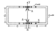 Figure P8.6.5
|
| 8.6.5 | Perfectly conducting electrodes are composed of sheets bent into
the shape of  's, as shown in Fig. P8.6.5. The length of the
system in the z direction is very large compared to the length 2a or
height d, so the fields can be regarded as two dimensional. The
insulating gaps have a width 's, as shown in Fig. P8.6.5. The length of the
system in the z direction is very large compared to the length 2a or
height d, so the fields can be regarded as two dimensional. The
insulating gaps have a width  that is small compared to all
dimensions. Passing through these gaps is a magnetic flux (per unit
length in the z direction) that is small compared to all
dimensions. Passing through these gaps is a magnetic flux (per unit
length in the z direction)  (t). One method of solution
is suggested by Example 6.6.3. (t). One method of solution
is suggested by Example 6.6.3.
| (a) | Find A in regions (a) and (b) to the right and left, respectively, of the plane x = 0.
|
| (b) | Sketch H.
|
|
| 8.6.6* | The wires comprising the winding shown in cross-section by Fig.
P8.6.6 carry current in the -z direction over the range 0 < x < a and
return this current over the range -a < x < 0. These windings extend
uniformly over the range 0 < y < b. Thus, the current density in the
region of interest is J = - ino sin ( x/a)iz, where i
is the current carried by each wire and |no sin ( x/a)iz, where i
is the current carried by each wire and |no sin ( x/a)| is the
number of turns per unit area. This region is surrounded by perfectly
conducting walls at y = 0 and y = b and at x = -a and x = a.
The length l in the z direction is much greater than either a or b. x/a)| is the
number of turns per unit area. This region is surrounded by perfectly
conducting walls at y = 0 and y = b and at x = -a and x = a.
The length l in the z direction is much greater than either a or b.
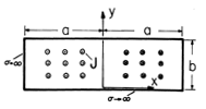 Figure P8.6.6
| (a) | Show that 
|
| (b) | Show that the inductance of the winding is

|
| (c) | Sketch H.
|
|
| 8.6.7 | In the configuration of Prob. 8.6.6, the rectangular region is
uniformly filled with wires that all carry their current in the z
direction. There are no of these wires per unit area. The
current carried by each wire is returned in the perfectly conducting
walls.
| (a) | Determine A.
|
| (b) | Assume that all the wires are connected to the wall by a
terminating plate at z = l and that each is driven by a current
source i(t) in the plane z = 0. Note that it has been assumed
that each of these current sources is the same function of time. What
is the voltage v(x, y, t) of these sources?
|
|
| 8.6.8 | In the configuration of Prob. 8.6.6, the turns are uniformly
distributed. Thus, no is a constant representing the number of
wires per unit area carrying current in the -z direction in the region
0 < x. Assume that the wire carrying current in the -z direction at the
location (x, y) returns the current at (-x, y).
| (a) | Determine A.
|
| (b) | Find the inductance L.
|
|
 d/2 and two in the negative z direction at x =
  d/2, y
= 0. (With the line charges representing line currents, the
cross-section is the same as shown in Fig. P4.4.3.)
Show that in the limit where r
  d, Az = - (
 o
id2/4
 )(r-2) cos 2
 . (Note that distances must be
approximated accurately to order d2.)

 that is much less than the inner radius b and outer
radius a. It supports a current density J = Jo i
 .
Show that along the z axis,


 direction.
With the wire driven by a current source, the resulting current
distribution is a surface current at r = R having the density
K = Ko sin
  i
i , where Ko is a given constant.
There are no other currents. Show that at the center of the
coil, H = (2Ko/3)iz.
 , where
Ko is again a constant. Find H at the center of the coil.
 , where Jo is a given constant. Outside
this region is free space and no other sources of H. Determine
H at the origin.


 for two infinitely long parallel thin wires carrying
currents i in opposite directions parallel to the z axis of a
Cartesian coordinate system and located along x =
  a. Show that
the lines
  = const in the x - y plane are circles.
 b and
that i(t) is so rapidly varying that the shell can be taken as
perfectly conducting. Show that in spherical coordinates, where R
 r < b
r < b

 d. The current
i(t) is so rapidly varying that the shell can be regarded as
perfectly conducting. What are
  and H in the region d
  r < a?
 o Ho is trapped
between perfectly conducting plane parallel plates that extend to
infinity to the left and right. At the origin on the lower plate is a
perfectly conducting half-cylinder of radius R.
 R, then


 R is attached
to the lower of two perfectly conducting plane parallel plates. The
hemisphere is centered at the origin of a spherical coordinate system
such as in Fig. P8.4.3, with

 . The magnetic field
intensity is uniform far from the hemisphere. Determine
  and
H.
 to z = +
 at (x, y) = (0, -h) is
a wire. The wire is parallel to a perfectly conducting plane at y = 0.
When t = 0, a current step i = I u-1(t) is applied in the +z
direction to the wire.

 (x2 + h2).

 z directions is shown in Fig. P8.4.6. Surrounded by free space,
a sheet of current has the surface current density Ko iz
uniformly distributed between x = b and x = a. The plane x = 0
is perfectly conducting.
 in the region 0 < x.


 o N2/8.
 at r = b and the boundary condition at r = a?
 , and hence H, in regions (a) and (b) outside
and inside the winding, respectively.
 returns the
current in the -z direction at -
 , what is the inductance of the
rotor coil? Why is it independent of the rotor position
  o?
o?
 is to be finite in the neighborhood
of r = R, Az must be continuous there.


 . Two of the sides are parallel to the z axis,
one at radius r = c and the other at r = 0. The other two, respectively,
join the ends of these segments, running radially from r = 0 to r = c.
 o H =
o H =  o [Hr(r, z)ir + Hz(r,
z)iz].
That is, the magnetic flux density is axially symmetric and does not
have a
  component.


 1,
show that the response has the dependence on b/a shown
in the plot of Fig. 8.6.11.
 1, the total current in the lower plate (21)
is consistent with a magnetic field intensity between the upper and
lower plates that is uniform (with respect to y) and hence equal to
(
 /b
/b o )ix. Note that


 's, as shown in Fig. P8.6.5. The length of the
system in the z direction is very large compared to the length 2a or
height d, so the fields can be regarded as two dimensional. The
insulating gaps have a width
  that is small compared to all
dimensions. Passing through these gaps is a magnetic flux (per unit
length in the z direction)
  (t). One method of solution
is suggested by Example 6.6.3.
 x/a)iz, where i
is the current carried by each wire and |no sin (
 x/a)| is the
number of turns per unit area. This region is surrounded by perfectly
conducting walls at y = 0 and y = b and at x = -a and x = a.
The length l in the z direction is much greater than either a or b.


