The sources of the magnetic fields considered in Chap. 8 were conduction currents associated with the motion of unpaired charge carriers through materials. Typically, the current was in a metal and the carriers were conduction electrons. In this chapter, we recognize that materials provide still other magnetic field sources. These account for the fields of permanent magnets and for the increase in inductance produced in a coil by insertion of a magnetizable material.
Magnetization effects are due to the propensity of the atomic constituents of matter to behave as magnetic dipoles. It is natural to think of electrons circulating around a nucleus as comprising a circulating current, and hence giving rise to a magnetic moment similar to that for a current loop, as discussed in Example 8.3.2.
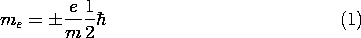
More surprising is the magnetic dipole moment found for individual electrons. This moment, associated with the electronic property of spin, is defined as the Bohr magneton
where e/m is the electronic charge-to-mass ratio, 1.76 x 10¹¹ coulomb/kg, and 2
is Planck's constant,
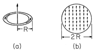
An estimate of the moment that would result if each atom or molecule of a material contributed only one Bohr magneton shows that the orbital and spin contributions from all the electrons comprising a typical solid had better tend to cancel or the resulting field effects would be prodigious indeed. Even if each atom or molecule is made to contribute only one Bohr magneton of magnetic moment, a magnetic field results comparable to that produced by extremely large conduction currents. To make this apparent, compare the magnetic field induced by a current loop having a radius R and carrying a current i (Fig. 9.0.la) to that from a spherical collection of dipoles (Fig. 9.0.1b), each having the magnetic moment of only one electron.
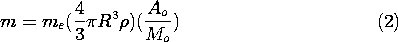
Figure 9.0.1 (a) Current i in loop of radius R gives dipole moment m. (b) Spherical material of radius R has dipole moment approximated as the sum of atomic dipole moments. In the case of the spherical material, we consider the net dipole moment to be simply the moment me of a single molecule multiplied by the number of molecules. The number of molecules per unit mass is Avogadro's number (A0 = 6.023 x 1026 molecules/kg-mole) divided by the molecular weight, Mo. The mass is the volume multiplied by the mass density
(kg/m3). Thus, for a sphere having radius R, the sum of the dipole moments is
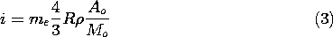
Suppose that the current loop shown in Fig. 9.0.1a has the same radius R as the sphere. What current i would give rise to a magnetic moment equal to that from the sphere of hypothetical material? If the moment of the loop, given by (8.3.19) as being m = i
R2, is set equal to that of the sphere, (2), it follows that i must be
Hence, for iron (where
Material magnetization can either be permanent or be induced by the application of a field, much as for the polarizable materials considered in Chap. 6. In most materials, the average moment per molecule that can be brought into play is much less than one Bohr magneton. However, highly magnetizable materials can produce net magnetic moments comparable to that estimated in (2).
The development of magnetization in this chapter parallels that for polarization in Chap. 6. Just as the polarization density was used in Sec. 6.1 to represent the effect of electric dipoles on the electric field intensity, the magnetization density introduced in Sec. 9.1 will account for the contributions of magnetic dipoles to the magnetic field intensity. The MQS laws and continuity conditions then collected in Sec. 9.2 are the basis for the remaining sections, and for Chap. 10 as well.
Because permanent magnets are so common, the permanent magnetization fields considered in Sec. 9.3 are more familiar than the permanent polarization electric fields of Sec. 6.3. Similarly, the force experienced as a piece of iron is brought into a magnetic field is common evidence of the induced magnetization described by the constitutive laws of Sec. 9.4.
The extensive analogy between polarization and magnetization makes most of the examples from Chap. 6 analogous to magnetization examples. This is especially true in Secs. 9.5 and 9.6, where materials are considered that have a magnetization that is linearly related to the magnetic field intensity. Thus, these sections not only build on the insights gained in the earlier sections on polarization, but give the opportunity to expand on both topics as well. The magnetic circuits considered in Sec. 9.7 are of great practical interest and exemplify an approximate way for the evaluation of fields in the presence of strongly magnetized materials. The saturation of magnetizable materials is of primary practical concern. The problems for Secs. 9.6 and 9.7 are an introduction to fields in materials that are magnetically nonlinear.
We generalize Faraday's law in Sec. 9.2 so that it can be used in this chapter to predict the voltage at the terminals of coils in systems that include magnetization. This generalization is used to determine terminal relations that include magnetization in Sec. 9.5. The examples in the subsequent sections study the implications of Faraday's law with magnetization included. As in Chap. 8, we confine ourselves in this chapter to examples that can be modeled using the terminal variables of perfectly conducting circuits. The MQS laws, generalized in Sec. 9.2 to include magnetization, form the basis for the discussion of electric fields in MQS systems that is the theme of Chap. 10.