In this and the next two sections, we study materials with the
linear magnetization characteristic of (9.4.4). With the
understanding that  is a prescribed function of position,
B =
  H, the MQS forms of Ampère's law and the flux
continuity law are


In this chapter, we assume that the current density J is confined to perfect conductors. We will find in Chap. 10 that a time-varying magnetic flux implies an electric field. Thus, wherever a conducting material finds itself in a time-varying field, there is the possibility that eddy currents will be induced. It is for this reason that the magnetizable materials considered in this and the next sections are presumed to be insulating. If the fields of interest vary slowly enough, these induced currents can be negligible.
Ferromagnetic materials are often metallic, and hence also conductors. However, materials can be made both readily magnetizable and insulating by breaking up the conduction paths. By engineering at the molecular or domain scale, or even introducing laminations of magnetizable materials, the material is rendered essentially free of a current density J. The considerations that determine the thickness of laminations used in transformers to prevent eddy currents will be taken up in Chap. 10.
In the regions outside the perfect conductors carrying the
current J of (1), H is irrotational and B is solenoidal.
Thus, we have a choice of representations. Either, as in Sec. 8.3, we
can use the scalar magnetic potential and let H = -
 ,
or we can follow the lead from Sec. 8.6 and use the vector potential
to represent the flux density by letting B =
  x A.
x A.
Where there are discontinuities in the permeability and/or thin coils modeled by surface currents, the continuity conditions associated with Ampère's law and the flux continuity law are used. With B expressed using the linear magnetization constitutive law, (1.4.16) and (9.2.10) become


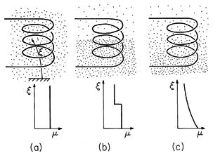
The classification of physical configurations given in Sec. 6.5
for linearly polarizable materials is equally useful here. In the
first of these, the region of interest is of uniform permeability.
The laws summarized by (1) and (2) are the same as for free space
except that  o is replaced by
  , so the results of Chap. 6
apply directly. Configurations made up of materials having
essentially uniform permeabilities are of the greatest practical
interest by far. Thus, piece-wise uniform systems are the theme of
Secs. 9.6 and 9.7. The smoothly inhomogeneous systems that are the
last category in Fig. 9.5.1 are of limited practical interest.
However, it is sometimes useful, perhaps in numerical simulations, to
regard the uniform and piece-wise uniform systems as special cases of
the smoothly nonuniform systems.

Inductance in the Presence of Linearly Magnetizable Materials
In the presence of linearly magnetizable materials, the magnetic flux density is again proportional to the excitation currents. If fields are produced by a single perfectly conducting coil, its inductance is the generalization of that introduced with (8.4.13).
The surface S spanning a contour defined by the perfectly conducting wire is the same as that shown in Figs. 8.4.3 and 8.4.4. The effect of having magnetizable material is, of course, represented in (5) by the effect of this material on the intensity, direction, and distribution of B =
H.
For systems in the first category of Fig. 9.5.1, where the entire region occupied by the field is filled by a material of uniform permeability
, the effect of the magnetization on the inductance is clear. The solutions to (1) and (2) for H are not altered in the presence of the permeable material. It then follows from (5) that the inductance is simply proportional to
.
Because it imposes a magnetic field intensity that never leaves the core material, the toroid of Example 9.4.1 is a special case of a piece-wise uniform magnetic material that acts as if all of space were filled with the magnetizable material. As shown by the following example, the inductance of the toroid is therefore also proportional to
.
Example 9.5.1. Inductance of a Toroid
If the toroidal core of the winding shown in Fig. 9.4.1 and used in the experiment of Fig. 9.4.3 were made a linearly magnetizable material, what would be the voltage needed to supply the driving current i? If we define the flux linkage of the driving coil as
1,
We now find the inductance L, where
1 = Li, and hence determine the required input voltage.
The flux linked by one turn of the driving coil is essentially the cross-sectional area of the toroid multiplied by the flux density. The total flux linked is this quantity multiplied by the total turns N1.
According to the linear constitutive law, the flux density follows from the field intensity as B =
H. For the toroid, H is related to the driving current i by (9.4.1), so
The desired relation is the combination of these last two expressions.
As predicted, the inductance is proportional to
. Although inductances are generally increased by bringing paramagnetic and especially ferromagnetic materials into their fields, the effect of introducing ferromagnetic materials into coils can be less dramatic than in the toroidal geometry for reasons discussed in Sec. 9.6. The dependence of the inductance on the square of the turns results because not only is the field induced by the current i proportional to the number of turns, but so too is the amount of the resulting flux that is linked by the coil.
Example 9.5.2. An Artificial Diamagnetic Material
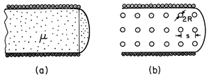
The cross-section of a long (ideally "infinite") solenoid filled with material of uniform permeability is shown in Fig. 9.5.2a. The azimuthal surface current K
results in an axial magnetic field intensity Hz = K
. We presume that the axial length d is very large compared to the radius a of the coil. Thus, the field inside the coil is uniform while that outside is zero. To see that this simple field solution is indeed correct, note that it is both irrotational and solenoidal everywhere except at the surface r = a, and that there the boundary conditions, (3) and (4), are satisfied.
Figure 9.5.2 (a) Solenoid of length d and radius a filled with material of uniform permeability . (b) Solenoid of (a) filled with artificial diamagnetic material composed of an array of metal spheres having radius R and spacing s.
For an n-turn coil carrying a current i, the surface current density K
= ni/d. Thus, the magnetic field intensity is related to the terminal current by
In the linearly magnetized core region, the flux density is Bz =
Hz, and so it is also uniform. As a result, the flux linked by each turn is simply
a2 Bz and the total flux linked by the coil is
Substitution from (1) then gives
where L is the inductance of the coil. Because the coil is assumed to be very long, its inductance is increased by a factor
/
o over that of a coil in free space, much as for the toroid of Example 9.5.1.
Now suppose that the permeable material is actually a cubic array of metal spheres, each having a radius R, as shown in Fig. 9.5.2b. The frequency of the current i is presumably high enough so that each sphere can be regarded as perfectly conducting in the MQS sense discussed in Sec. 8.4. The spacing s of the spheres is large compared to their radius, so that the field of one sphere does not produce an appreciable field at the positions of its neighbors. Each sphere finds itself in an essentially uniform magnetic field.
The dipole moment of the currents induced in a sphere by a magnetic field that is uniform at infinity was calculated in Example 8.4.3, (8.4.21).
Because the induced currents must produce a field that bucks out the imposed field, a negative moment is induced by a positive field.
By definition, the magnetization density is the number of magnetic moments per unit volume. For a cubic array with spacing s between the sphere centers, the number per unit volume is s-3. Thus, the magnetization density is simply
Comparison of this expression to (9.4.3), which defines the susceptibility
m, shows that
As we might have expected from the antiparallel moment induced in a sphere by an imposed field, the susceptibility is negative. The permeability, related to
m by (9.4.4), is therefore less than 1.
The perfectly conducting spheres effectively reduce the cross-sectional area of the flux, as suggested by Fig. 9.5.3, and hence reduce the inductance. With the introduction of the array of metal spheres, the inductance goes from a value given by (12) with
=
o to one with
given by (16).
Figure 9.5.3 Inductance of the coil in Fig. 9.5.2b is decreased because perfectly conducting spheres tend to reduce its effective cross-sectional area. Faraday's law of induction is also responsible for diamagnetism due to atomic moments. Instead of inducing circulating conduction currents in a metal sphere, as in this example, the time-varying field induces changes in the orbits of electrons about the nucleus that, on the average, contribute an antiparallel magnetic moment to the atom.
The following demonstration is the MQS analog of the EQS Demonstration 6.6.1. In the latter, a measurement was made of the change in capacitance caused by inserting an artificial dielectric between capacitor plates. Here the change in inductance is observed as an artificial diamagnetic material is inserted into a solenoid. Although the spheres are modeled as perfectly conducting in both demonstrations, we will find in Chap. 10 that the requirements to justify this assumption in this MQS example are very different from those for its EQS counterpart.
Demonstration 9.5.1. Artificial Diamagnetic Material
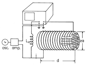
The experiment shown in Fig. 9.5.4 measures the change in solenoid inductance when an array of conducting spheres is inserted. The coil is driven at the angular frequency
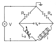
by an oscillator-amplifier. Over the length d shown in the figure, the field tends to be uniform. The circuit shown schematically in Fig. 9.5.5 takes the form of a bridge with the inductive reactance of L2 used to balance the reactance of the central part of the empty solenoid.
Figure 9.5.4 Experiment to measure the decrease of inductance that results when the artificial diamagnetic array of Fig. 9.5.2b is inserted into a solenoid.
Figure 9.5.5 Bridge used to measure the change in inductance in the experiment of Fig. 9.5.4. The input resistances of the oscilloscope's balanced amplifiers, represented by Rs, are large compared to the inductor reactances. These branches dominate over the inductive reactances in determining the current through the inductors and, as a result, the inductor currents remain essentially constant as the inductances are varied. With the reactance of the inductor L2 balancing that of the empty solenoid, these currents are equal and the balanced amplifier voltage vo = 0. When the array of spheres is inserted into the solenoid, the currents through both legs remain essentially constant. Thus, the resulting voltage vo is the change in voltage across the solenoid caused by its change in inductance
L.
In the latter expression, the current and voltage indicated by a circumflex are either peak or rms sinusoidal steady state amplitudes. In view of (12), this expression becomes
In terms of the sphere radius and spacing, the change in permeability is given by (16), so the voltage measured by the balanced amplifiers is
To evaluate this expression, we need only the frequency and amplitude of the coil current, the number of turns in the length d, and other dimensions of the system.
Induced Magnetic Charge: Demagnetization
The complete analogy between linearly polarized and linearly magnetized materials is profitably carried yet another step. Magnetic charge is induced where
is spatially varying, and hence the magnetizable material can introduce sources that revise the free space field distribution. In the linearly magnetizable material, the distribution of these sources is not known until after the fields have been determined. However, it is often helpful in qualitatively predicting the field effects of magnetizable materials to picture the distribution of induced magnetic charges.
Using a vector identity, (2) can be written
Rearrangement of this expression shows that the source of
oH, the magnetic charge density, is
Most often we deal with piece-wise uniform systems where variations in
are confined to interfaces. In that case, it is appropriate to write the continuity of flux density condition in the form
where
sm is the magnetic surface charge density. The following illustrates the use of this relation.
Illustration. The Demagnetization Field
A sphere of material having uniform permeability
is placed in an initially uniform upward-directed field. It is clear from (21) that there are no distortions of the uniform field from magnetic charge induced in the volume of the material. Rather, the sources of induced field are located on the surface where the imposed field has a component normal to the permeability discontinuity. It follows from (22) that positive and negative magnetic surface charges are induced on the top and bottom parts of the surface, respectively.
The H field caused by the induced magnetic surface charges originates at the positive charge at the top and terminates on the negative charge at the bottom. This is illustrated by the magnetization analog of the permanently polarized sphere, considered in Example 6.3.1. Our point here is that the field resulting from these induced magnetic surface charges tends to cancel the one imposed. Thus, the field intensity available to magnetize the material is reduced.
The remarks following (6.5.11) apply equally well here. The roles of E, D, and
are taken by H, B, and
. In regions of uniform permeability, (1) and (2) are the same laws considered in Chap. 8, and where the current density is zero, Laplace's equation governs. As we now consider piece-wise nonuniform systems, the effect of the material is accounted for by the continuity conditions.


