The availability of relatively inexpensive magnetic materials, with magnetic susceptibilities of the order of 1000 or more, allows the production of high magnetic flux densities with relatively small currents. Devices designed to exploit these materials include compact inductors, transformers, and rotating machines. Many of these are modeled as the magnetic circuits that are the theme of this section.
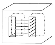
A magnetic circuit typical of transformer cores is shown in Fig. 9.7.1. A core of high permeability material has a pair of rectangular windows cut through its center. Wires passing through these windows are wrapped around the central column. The flux generated by this coil tends to be guided by the magnetizable material. It passes upward through the center leg of the material, and splits into parts that circulate through the legs to left and right.
Example 9.6.2, with its highly permeable sphere excited by a small
coil, offered the opportunity to study the trapping of magnetic
flux. Here, as in that case with  b /
b / a
a  1,
the flux density inside the core tends to be tangential
to the surface. Thus, the magnetic flux density is guided by the
material and the field distribution within the core tends to be
independent of the exterior configuration.
In situations of this type, where the ducting of the magnetic flux makes it possible to approximate the distribution of magnetic field, the MQS integral laws serve much the same purpose as do Kirchhoff's laws for electrical circuits.
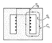
The MQS form of Ampère's integral law applies to a contour, such as C1 in Fig. 9.7.2, following a path of circulating magnetic flux.

The surface enclosed by this contour in Fig. 9.7.2 is pierced N times by the current carried by the wire, so the surface integral of the current density on the right in (1) is, in this case, Ni. The same equation could be written for a contour circulating through the left leg, or for one circulating around through the outer legs. Note that the latter would enclose a surface S through which the net current would be zero.
If Ampère's integral law plays a role analogous to Kirchhoff's voltage law, then the integral law expressing continuity of magnetic flux is analogous to Kirchhoff's current law. It requires that through a closed surface, such as S2 in Fig. 9.7.2, the net magnetic flux is zero.

As a result, the flux entering the closed surface S2 in Fig. 9.7.2 through the central leg must be equal to that leaving to left and right through the upper legs of the magnetic circuit. We will return to this particular magnetic circuit when we discuss transformers.
Example 9.7.1. The Air Gap Field of an Electromagnet
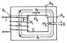
The magnetic circuit of Fig. 9.7.3 might be used to produce a high magnetic field intensity in the narrow air gap. An N-turn coil is wrapped around the left leg of the highly permeable core. Provided that the length g of the air gap is not too large, the flux resulting from the current i in this winding is largely guided along the magnetizable material.
Figure 9.7.3 Cross-section of magnetic circuit used to produce a magnetic field intensity Hg in an air gap. By approximating the fields in sections of the circuit as being essentially uniform, it is possible to use the integral laws to determine the field intensity in the gap. In the left leg, the field is approximated by the constant H1 over the length l1 and cross-sectional area A1. Similarly, over the lengths l2, which have the cross-sectional areas A2, the field intensity is approximated by H2. Finally, under the assumption that the gap width g is small compared to the cross-sectional dimensions of the gap, the field in the gap is represented by the constant Hg. The line integral of H in Ampère's integral law, (1), is then applied to the contour C that follows the magnetic field intensity around the circuit to obtain the left-hand side of the expression
The right-hand side of this equation represents the surface integral of J
d a for a surface S having this contour as its edge. The total current through the surface is simply the current through one wire multiplied by the number of times it pierces the surface S.
We presume that the magnetizable material is operated under conditions of magnetic linearity. The constitutive law then relates the flux density and field intensity in each of the regions.
Continuity of magnetic flux, (2), requires that the total flux through each section of the circuit be the same. With the flux densities expressed using (4), this requires that
Our objective is to determine Hg. To that end, (5) is used to write
and these relations used to eliminate H1 and H2 in favor of Hg in (3). From the resulting expression, it follows that
Note that in the limit of infinite core permeability, the gap field intensity is simply Ni/g.
If the magnetic circuit can be broken into sections in which the field intensity is essentially uniform, then the fields may be determined from the integral laws. The previous example is a case in point. A more general approach is required if the core is of complex geometry or if a more accurate model is required.
We presume throughout this chapter that the magnetizable material is sufficiently insulating so that even if the fields are time varying, there is no current density in the core. As a result, the magnetic field intensity in the core can be represented in terms of the scalar magnetic potential introduced in Sec. 8.3.

According to Ampère's integral law, (1), integration of
H  ds around a closed contour must be equal to the
"Ampère turns" Ni passing through the surface spanning the
contour. With H expressed in terms of
  , integration from
(a) to (b) around a contour such as C in Fig. 9.7.4, which
encircles a net current equal
to the product of the turns N and the current per turn i, gives
 a -
a -  b
b 

 = Ni. With (a) and (b) adjacent
to each other, it is clear that
  is multiple-valued. To specify the
principal value of this multiple-valued function we must introduce a
discontinuity in
  somewhere along the contour. In the circuit of
Fig. 9.7.4, this discontinuity is defined to occur across the surface
Sd.
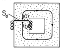
To make the line integral of H  ds from any point
just above the surface Sd around the circuit to a point just below
the surface equal to Ni, the potential is required to suffer a
discontinuity
 = Ni across Sd. Everywhere inside the
magnetic material,
  satisfies Laplace's equation. If, in
addition,
the normal flux density on the walls of the magnetizable material is
required to vanish, the distribution of
  within the core is
uniquely determined. Note that only the discontinuity in
  is
specified on the surface Sd. The magnitude of
  on one side
or the other is not specified. Also, the normal derivative of
  ,
which is proportional to the normal component of H, must be
continuous across Sd.
The following simple example shows how the scalar magnetic potential can be used to determine the field inside a magnetic circuit.
Example 9.7.2. The Magnetic Potential inside a Magnetizable Core
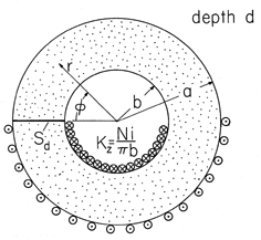
The core of the magnetic circuit shown in Fig. 9.7.5 has outer and inner radii a and b, respectively, and a length d in the z direction that is large compared to a. A current i is carried in the z direction through the center hole and returned on the outer periphery by N turns. Thus, the integral of H
ds over a contour circulating around the magnetic circuit must be Ni, and a surface of discontinuity Sd is arbitrarily introduced as shown in Fig. 9.7.5. With the boundary condition of no flux leakage,

/
r = 0 at r = a and at r = b, the solution to Laplace's equation within the core is uniquely specified.
Figure 9.7.5 Magnetic circuit consisting of a core having the shape of a circular cylindrical annulus with an N-turn winding wrapped around half of its circumferential length. The length of the system into the paper is very long compared to the outer radius a. In principle, the boundary value problem can be solved even if the geometry is complicated. For the configuration shown in Fig. 9.7.5, the requirement of no radial derivative suggests that
is independent of r. Thus, with A an arbitrary coefficient, a reasonable guess is
The coefficient A has been selected so that there is indeed a discontinuity Ni in
between
= 2
and
= 0.
The magnetic field intensity given by substituting (9) into (8) is
Note that H is continuous, as it should be.
Now that the inside field has been determined, it is possible, in turn, to find the fields in the surrounding free space regions. The solution for the inside field, together with the given surface current distribution at the boundary between regions, provides the tangential field at the boundaries of the outside regions. Within an arbitrary constant, a boundary condition on
is therefore specified. In the outside regions, there is no closed contour that both stays within the region and encircles current. In these regions,
is continuous. Thus, the problem of finding the "leakage" fields is reduced to finding the boundary value solution to Laplace's equation.
This inside-outside approach gives an approximate field distribution that is justified only if the relative permeability of the core is very large. Once the outside field is approximated in this way, it can be used to predict how much flux has left the magnetic circuit and hence how much error there is in the calculation. Generally, the error will be found to depend not only on the relative permeability but also on the geometry. If the magnetic circuit is composed of legs that are long and thin, then we would expect the leakage of flux to be large and the approximation of the inside-outside approach to become invalid.
Electrical Terminal Relations and Characteristics
Practical inductors (chokes) often take the form of magnetic circuits. With more than one winding on the same magnetic circuit, the magnetic circuit serves as the core of a transformer. Figure 9.7.6 gives the schematic representation of a transformer. Each winding is modeled as perfectly conducting, so its terminal voltage is given by (9.2.12).

However, the flux linked by one winding is due to two currents. If the core is magnetically linear, we have a flux linked by the first coil that is the sum of a flux linkage L11 i1 due to its own current and a flux linkage L12 due to the current in the second winding. The situation for the second coil is similar. Thus, the flux linkages are related to the terminal currents by an inductance matrix.

The coefficients Lij are functions of the core and coil geometries and properties of the material, with L11 and L22 the familiar self-inductances and L12 and L21 the mutual inductances.
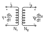
The word "transformer" is commonly used in two ways, each often represented schematically, as in Fig. 9.7.6. In the first, the implication is only that the terminal relations are as summarized by (12). In the second usage, where the device is said to be an ideal transformer, the terminal relations are given as voltage and current ratios. For an ideal transformer,

Presumably, such a device can serve to step up the voltage while stepping down the current. The relationships between terminal voltages and between terminal currents is linear, so that such a device is "ideal" for processing signals.
The magnetic circuit developed in the next example is that of a typical transformer. We have two objectives. First, we determine the inductances needed to complete (12). Second, we define the conditions under which such a transformer operates as an ideal transformer.
Example 9.7.3. A Transformer
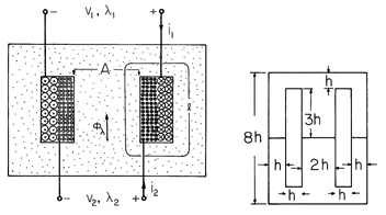
The core shown in Fig. 9.7.7 is familiar from the introduction to this section, Fig. 9.7.1. The "windows" have been filled up by a pair of windings, having the turns N1 and N2, respectively. They share the center leg of the magnetic circuit as a common core and generate a flux that circulates through the branches to either side.
Figure 9.7.7 In a typical transformer, coupling is optimized by wrapping the primary and secondary on the same core. The inset shows how full use is made of the magnetizable material in the core manufacture. The relation between the terminal voltages for an ideal transformer depends only on unity coupling between the two windings. That is, if we call
the magnetic flux through the center leg, the flux linking the respective coils is
These statements presume that there is no leakage flux which would link one coil but bypass the other.
In terms of the magnetic flux through the center leg, the terminal voltages follow from (14) as
From these expressions, without further restrictions on the mode of operation, follows the relation between the terminal voltages of (13).
We now use the integral laws to determine the flux linkages in terms of the currents. Because it is desirable to minimize the peak magnetic flux density at each point throughout the core, and because the flux through the center leg divides evenly between the two circuits, the cross-sectional areas of the return legs are made half as large as that of the center leg.
3 To optimize the usage of core material, the relative dimensions are often taken as in the inset to Fig. 9.7.7. Two cores are cut from rectangular sections measuring 6h x 8h. Once the windows have been removed, the rectangle is cut in two, forming two "E" cores which can then be combined with the "I's" to form two complete cores. To reduce eddy currents, the core is often made from varnished laminations. This will be discussed in Chap. 10. As a result, the magnitude of B, and hence H, can be approximated as constant throughout the core. [Note that we have now used the flux continuity condition of (2).]
With the average length of a circulating magnetic field line taken as l, Ampère's integral law, (1), gives

In view of the presumed magnetic linearity of the core, the flux through the cross-sectional area A of the center leg is

and it follows from these last two expressions that

Multiplication by the turns N1 and then N2, respectively, gives
the flux linkages  1 and
1 and  2.
2.


Comparison of this expression with (12) identifies the self- and mutual inductances as

Note that the mutual inductances are equal. In Sec. 11.7, we shall see that this is a consequence of energy conservation. Also, the self-inductances are related to either mutual inductance by

Under what conditions do the terminal currents obey the relations for an "ideal transformer"?
Suppose that the (1) terminals are selected as the "primary" terminals of the transformer and driven by a current source I(t), and that the terminals of the (2) winding, the "secondary," are connected to a resistive load R. To recognize that the winding in fact has an internal resistance, this load includes the winding resistance as well. The electrical circuit is as shown in Fig. 9.7.8.

The secondary circuit equation is

and using (12) with i1 = I, it follows that the secondary current i2 is governed by

For purposes of illustration, consider the response to a drive that is
in the sinusoidal steady state. With the drive angular frequency
equal to  , the response has the same time dependence in the
steady state.

Substitution into (23) then shows that the complex amplitude of the response is

The ideal transformer-current relation is obtained if

In that case, (25) reduces to

When the ideal transformer condition, (26), holds, the first term on the left in (23) overwhelms the second. What remains if the resistance term is neglected is the statement

We conclude that for ideal transformer operation, the flux linkages are negligible. This is crucial to having a transformer behave as a linear device. Whether represented by the inductance matrix of (12) or by the ideal relations of (13), linear operation hinges on having a linear relation between B and H in the core, (17). By operating in the regime of (26) so that B is small enough to avoid saturation, (17) tends to remain valid.


