Laws and Continuity Conditions with Magnetization
 M. Find
 m and
m and  sm.
sm.
 + iy cos
 ]. In the surrounding region, the material forces H to be
zero. (In Sec. 9.6, it will be seen that such a
material is one of infinite permeability.)
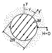
| (a) | Show that if H = 0 everywhere, both Ampère's law and (9.2.2) are satisfied. |
| (b) | Suppose
that the cylinder rotates with the angular velocity  so that so that
 = =  t. Then, B is time varying even though there is no
H. A one-turn rectangular coil having depth d in the z direction
has legs running parallel to the z axis in the +z direction at x
= -R, y = 0 and in the -z direction at x = R, y = 0.
The other legs of the coil
are perpendicular to the z axis. Show that the voltage induced at the
terminals of this coil by the time-varying magnetization density is v
= - t. Then, B is time varying even though there is no
H. A one-turn rectangular coil having depth d in the z direction
has legs running parallel to the z axis in the +z direction at x
= -R, y = 0 and in the -z direction at x = R, y = 0.
The other legs of the coil
are perpendicular to the z axis. Show that the voltage induced at the
terminals of this coil by the time-varying magnetization density is v
= - o 2 Rd Mo o 2 Rd Mo  sin sin  t. t.
|
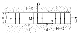
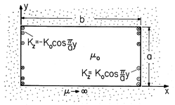
 (x - Ut), as shown in Fig. P9.2.2. The
regions above and below are constrained so that H = 0 there and so
that the integral of H
  ds between y = 0 and y = a
is zero. (In
Sec. 9.7, it will be clear that these materials could be the pole
faces of a highly permeable magnetic circuit.)
| (a) | Show that Ampère's law and (9.2.2) are satisfied if H = 0 throughout the magnetizable layer of material. |
| (b) | A one-turn rectangular coil is located in the y = 0 plane, one leg running in the +z direction at x = -d (from z = 0 to z = l) and another running in the -z direction at x = d (from z = l to z = 0). What is the voltage induced at the terminals of this coil by the motion of the layer? |
Permanent Magnetization
 z
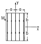
directions than either of its cross-sectional dimensions 2a and 2b.
Show that the scalar magnetic potential is
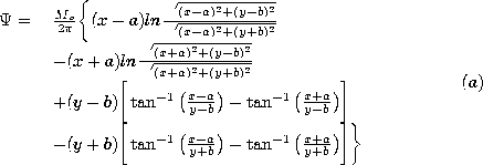
 x) exp (-
 y)iy, where
  and
and  are given positive constants.
The half-space y < 0 is free space. Show that

 x) exp (
 y)ix, where
  and
and  are positive constants.
The half-space y > 0 is free space. Find the scalar magnetic
potential.
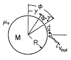

| (a) | Determine the magnetic potential  . .
|
| (b) | A magnetic pickup is
comprised of an N-turn coil located at  = =  /2. This coil
has a dimension a in the /2. This coil
has a dimension a in the  direction that is small compared to the
periodicity length 2 direction that is small compared to the
periodicity length 2 R/p in that direction. Every turn is
essentially at the radius d + R. Determine the output voltage
vout when the cylinder rotates, R/p in that direction. Every turn is
essentially at the radius d + R. Determine the output voltage
vout when the cylinder rotates,  = =  t. t.
|
| (c) | Show that if the density of information on the cylinder is to be high (p is to be high), then the spacing between the coil and the cylinder, d, must be small. |
Magnetization Constitutive Laws
 H), where M and H
are collinear.
| (a) | Show that the B-H characteristic is of the type illustrated in Fig. 9.4.4. |
| (b) | Show that if i = io cos  t, the output voltage
is t, the output voltage
is
 |
| (c) | Show that the characteristic is essentially linear, provided
that  N1 io/2 N1 io/2 R R  1. 1.
|
| (a) | B(t) |
| (b) | the output voltage v(t). |
Fields in the Presence of magnetically Linear Insultating Materials
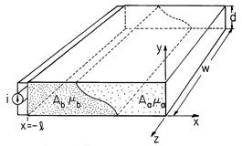
 shape to make a
one-turn inductor, as shown in Fig. P9.5.1. The width w is much
larger than the dimensions in the x - y plane. The region inside the
inductor is filled with two linearly magnetizable materials having
permeabilities
  a and
a and  b, respectively. The
cross-section of the system in any x - y plane is the same. The
cross-sectional areas of the magnetizable materials are Aa and
Ab, respectively. Given that the current i(t) is uniformly
distributed over the width w of the inductor, show that
H = (i/w)iz in both of the magnetizable materials. Show
that the inductance L = (
 a Aa +
  b Ab)/w.
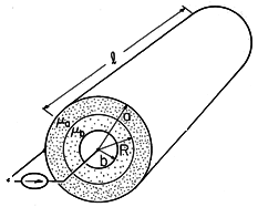
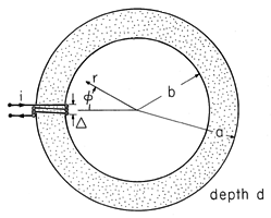
| (a) | Determine H in the annulus. (A simple solution can be shown to satisfy all the laws and continuity conditions.) |
| (b) | Find the inductance. |
 = -
= -  m x/l, where
  m is a given
constant. Show that the inductance is L = d
 m l/2w.
 =
=  m (r/b),
where
  m is a given constant. Determine the inductance.
| (a) | Assume that in the regions (a) and (b), respectively, H = i A/r and H = i A/r and H = i C/r, and show that
with A and C functions of time,
these fields satisfy Ampère's law and the flux continuity law in the
respective regions. C/r, and show that
with A and C functions of time,
these fields satisfy Ampère's law and the flux continuity law in the
respective regions.
|
| (b) | Use the flux continuity condition at the
interfaces between regions to show that C = ( a / a / b)A. b)A.
|
| (c) | Use Ampère's integral law to relate C and A to the total current i in the inner conductor. |
| (d) | Show that the inductance is L = l  a
ln(a/b)/[ a
ln(a/b)/[ + (2 + (2 - -  ) )  a / a / b ]. b ].
|
| (e) | Show that the surface current densities at r = b adjacent
to regions (a) and (b), respectively, are Kz = A/b and Kz = C/b.
|
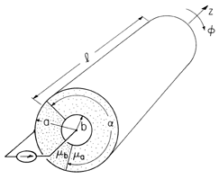
 a, while
  =
=  b in
the range a < z < w. Determine the inductance.
Fields in Piece-Wise Uniform Magnetically Linear Materials
 z ix. Region (a), where y > 0,
is free space, while region (b), where y < 0, has permeability
  .
.
| (a) | Show that
 |
| (b) | Now consider the same problem, but assume at the outset
that the material in region (b) has infinite permeability. Show that
it agrees with the limit    of the first
expression of part (a). of the first
expression of part (a).
|
| (c) | In turn, use the result of part (b) as a starting point in
finding an approximation to  in the highly permeable material.
Show that this result agrees with the limit of the second result of
part (a) where in the highly permeable material.
Show that this result agrees with the limit of the second result of
part (a) where    o. o.
|
 y/2d). The system extends to infinity in the
  x
directions and is two dimensional.
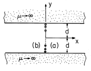
| (a) | In terms of  , what are the boundary conditions at y = , what are the boundary conditions at y =  d. d.
|
| (b) | What continuity conditions relate  in regions (a) and
(b) where they meet at x = 0? in regions (a) and
(b) where they meet at x = 0?
|
| (c) | Determine  . .
|
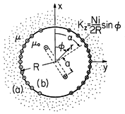
 which can be
considered as extending to infinity. A winding at r = R is driven by
the current i and has turns density (N/2R) sin
  (turns per
unit length in the
  direction). Thus, at r = R, there is a
current density K = (N/2R) i sin
  iz.
iz.

| (a) | Show that |
| (b) | An n-turn coil having a spacing between conductors of 2a
is now
placed at the center. The magnetic axis of this coil is inclined at
the angle  relative to the x axis. This coil has length l in
the z direction. Show that the mutual inductance between this coil and
the one at r = R is Lm = relative to the x axis. This coil has length l in
the z direction. Show that the mutual inductance between this coil and
the one at r = R is Lm =  o a ln N cos o a ln N cos  /R[1 + ( /R[1 + ( o
/ o
/ )]. )].
|
infinite, and determine the vector potential in the air gap.
| (a) | Assume that the permeabilities of the rotor and stator are |
| (b) | Determine the
self-inductances Ls and Lr and magnitude of the peak mutual
inductance, M, in (11.7.26). Assume that the current in the +z
direction at  is returned at is returned at  + +  . .
|
 z directions.
Region (a), where y > 0, is free space. In region (b), where y < 0,
the material has uniform permeability
  .
.
images to determine the fields in the two regions.
| (a) | Use the method of |
| (b) | Now assume that    o and find H in the
upper region, assuming at the outset that o and find H in the
upper region, assuming at the outset that    . .
|
| (c) | In turn, use
this approximate result to find the field in the permeable material.
|
| (d) | Show that the results of (b) and (c) are consistent with
those from the exact analysis in the limit where    o. o.
|
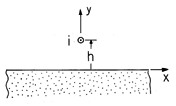
 o H, where
i is a vector having the direction and magnitude of the current
i(t), and H does not include the self-field of the line current.
f =  o iy i2/4
 h.
h.
| (a) | Show that if the material is a perfect conductor, |
| (b) | Show that if the material is infinitely permeable, f
= -  o iy i2/4 o iy i2/4 h. h.
|
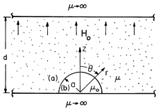
 is bounded from above
and below by regions of infinite permeability, as shown in Fig.
P9.6.7. With its center at the origin and on the surface of the lower
infinitely permeable material is a hemispherical cavity of free space
having radius a that is much less than d. A field that has the uniform
intensity Ho far from the hemispherical surface is imposed in the
z direction.
approximate magnetic potential in the magnetizable material is
 = - Ho a[(r/a) + (a/r)2/2] cos
  .
.
| (a) | Assume    o and show that the o and show that the
|
| (b) | In turn, show that the
approximate magnetic potential inside the hemisphere is
 = - 3Ho z/2. = - 3Ho z/2.
|

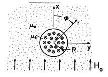
 a. A conductor passing through
this hole has permeability
  b and carries the uniform current
density J = Jo iz, as shown in Fig. P9.6.10. A field that
is uniform far from the hole, where it is given by H = Ho ix,
is applied by external means. Show that for r < R, and R < r,
respectively,


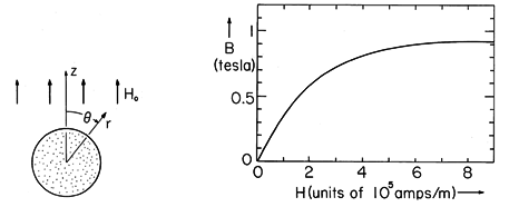
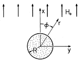
| (a) | Assume that the magnetization density is M = M iz, |
| (b) | Draw this load line in the B-H plane, showing that it
is a straight line with intercepts 3Ho/2 and 3 o Ho with the H
and B axes, respectively. o Ho with the H
and B axes, respectively.
|
| (c) | Show how (B, H) in the sphere are
determined, given the applied field intensity Ho, by graphically
finding the point of intersection between the B - H curve of Fig.
P9.6.11 and (a).
|
| (d) | Show that if Ho = 4 x 10⁵ A/m, B = 0.75 tesla
and H = 3.1 x 10⁵ A/m.
|
Magnetic Circuits
 in the
  direction that
is small compared to dimensions of interest. Assume that the core has
a permeability
  that is very large compared to
  o.
o.
(with  defined to be zero at
  =
=  ) are
) are

| (a) | Show that the approximate H and  inside the core inside the core
|
| (b) | Show that the approximate magnetic potential in the central
region is
 |
 in the
region outside the core, r > a.
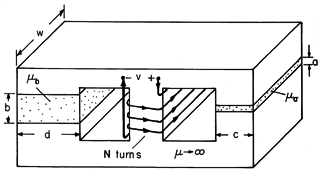
 a and
a and
 b, respectively, and the gap lengths a and b are small compared
to the other dimensions of these sections. Show that the inductance
L = N2 w[(
 b d/b) + (
 a c/a)].
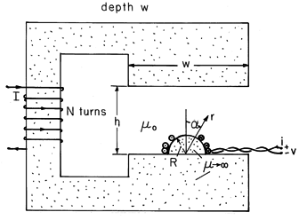
 , where n is the total number of turns.
Given that R
  h
h  w, find the mutual inductance of the two coils.


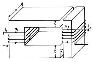
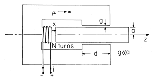
 , is limited in range so that the ends of the rod are
always well inside the ends of the stator. Thus, H in each of
the air gaps is essentially uniform. Determine the inductance
matrix, (9.7.12).
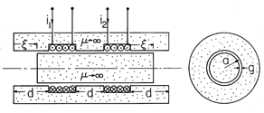
 that is much less than that of the sides but
nevertheless much greater than
  o. Coils having
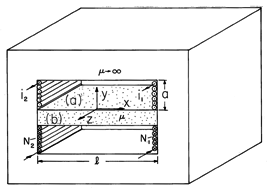
total turns N1 and N2, respectively, are wound around the
center leg. These have evenly distributed turns in the planes x =
l/2 and x = -l/2, respectively. The regions above and below the
center leg are free space.
coordinates. As far as
  is concerned inside the center leg,
what boundary conditions must
  satisfy if the central leg is
treated as the "inside" of an "inside-outside" problem?
| (a) | Define  = 0 at the origin of the given = 0 at the origin of the given
|
| (b) | What is  in the center leg? in the center leg?
|
| (c) | What boundary conditions must  satisfy in region
(a)? satisfy in region
(a)?
|
| (d) | What is  , and hence H, in region (a)? (A simple
exact solution is suggested by Prob. 7.5.3.) For the case where
N1 i1 = N2 i2, sketch , and hence H, in region (a)? (A simple
exact solution is suggested by Prob. 7.5.3.) For the case where
N1 i1 = N2 i2, sketch  and H in regions (a) and
(b). and H in regions (a) and
(b).
|
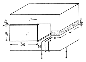
 , one to the right of length l2 and the
other to the left of length l1. This second leg has
wrapped on its periphery a metal strap having thickness
 w, conductivity
  , and height l1. With a terminal current
i = io cos
  t, determine H within the left leg.

| (a) | Show that the load line for the circuit is |
| (b) | For N = 500, d = 1 cm, l1 = 0.8 m, l2 = 0.2 m, and i = 10 amps, find the flux density B in its air gap. |
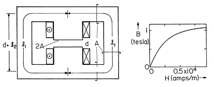
| (a) | Determine the load line relation between Hb, |
| (b) | If Ni/a = 0.5 x 10⁶ amps/m and b/a = 1, what is M, and hence B? |


