M.I.T. DEPARTMENT OF EECS
6.033 - Computer System Engineering (Spring 2004)
Design Project 2 - Mars Rover
Assignment
There are three deliverables for 6.033 Design Project #2 (details
below):
- a design proposal not to exceed 800 words (~2 pages), due on
April 13,
- a report not to exceed 5000 words (~12 pages), including an
executive summary, due on May 6th, and
- a presentation on May 11th (details will be given as the date
approaches).
On this project, you will work in teams of 3 students (all of whom must
have the same
recitation instructor). Send your
list of team members to your recitation instructor via email by
11:59 PM on April 5.
Each team
should submit 2 copies of the proposal (one for your recitation
instructor and one for your TA).
0. Updates
This design project was last updated April 25, 2004. For more
information, please see the version history
and FAQ.
1. Introduction
Distributed Rovers: Fast, Cheap, and Out of Control
The recent success of The
National Aeronautics and Space Administration's (NASA's) Mars rovers,
Spirit and Opportunity, has led NASA to begin planning
another robotic mission to Mars. This time, NASA engineers have
decided to send 50 small,
cheap rovers that will be able to spread
out and explore a 12-kilometer diameter impact crater. Because
these rovers are small and inexpensive, they have limited hardware
capabilities. In particular, NASA has decided not to equip the
rovers
with costly communication hardware that can transmit off of the
planet. Instead, rovers are equipped only with short range
radios, capable of transmitting a hundred meters at a time at low data
rates. To get the data off-planet, rovers must navigate to a
control center in the middle of the crater and radio data to
it. The control center, which is much more expensive and
fault-tolerant, then uses a powerful radio to
contact Earth. The advantage of this design is that
the costly control center is stationary, so can be large and well
protected. Additionally, lack of moving parts make
the control center less failure prone, since mechanical parts tend to
fail much earlier than other components. Furthermore, although
rovers
are individually unreliable, their large number means it will take a
long time for all of them to fail, and that a large portion of the
crater can be explored.
Your job is to design the command and communication systems for
the
rovers and the control center. NASA engineers have already taken
care of the hardware design and many of the low-level robotics
problems. Each rover is equipped with a navigational system that
can guide the rover to a particular location on the planet's surface,
as
well as a set of low-level communications primitives that can broadcast
radio messages (details on
these subsystems are given below). You must integrate these
components into a larger system that provides three core functions:
- Mission Distribution. NASA
will periodically upload new "missions" to the control center for
rovers to execute. Each mission consists of a list of geographic
coordinates to visit, as well as a number of "experiments" to
run.
Experiments consist of tasks such as taking a photograph at a certain
heading or obtaining a mineral sample. Details of the mission
format are given below. You must ensure that missions are
distributed from the control center to rovers such that any missions
NASA uploads will eventually be executed (assuming there are still any
working rovers.)
- Mission Execution. Once
a rover has been given one or more missions, it can begin executing
them. To complete a mission, rovers will have to travel long
distances, out of radio communications range of other rovers or the
control center. This travel time can take days or hours. Each
mission experiment can also take many hours to complete.
- Result Collection.
Eventually, after completing part or all of a mission,
rovers should deliver their data back to the control center.
Rovers may pass mission results to other rovers, rather than
delivering them directly to the control center.
There are a number of additional problems and issues that you must
consider when designing your solution. These include:
- Rover failure. A
rover can permanently fail for one of several reasons (for
example, batteries can malfunction and cease to charge, software
can crash, etc.) The control center needs to detect that a rover
has failed
and reallocate its missions to other rovers. It is also
possible that a rover can fail while communicating with the control
center or another rover; you must design your system to account
for such failures.
- Unreliable Communication.
Because messages can be lost or garbled when communicating, you must
devise a way of making communications reliable.
- Faulty Sensors. The
sensors used in some experiments will produce incorrect readings.
NASA identifies experiments where this is particularly likely to
happen; you will need to devise a method for reducing the
probability of delivering incorrect data in such cases.
- Mission amendments. NASA
engineers will sometimes change the specifications of ("amend")
missions that have already been uploaded to the control center.
Some of these amendments will be to missions that have already been
distributed to and partially or completely executed by rovers.
Amendments do not usually invalidate an entire mission but instead add
additional experiments or alter a few existing experiments. Amendments
do not apply to missions that have passed their commit point. The
commit point of a mission is when the Control Center confirms that it
has accepted all of that mission's results.
The
mission and amendment format is given below.
- Competing Missions. The
European Space Agency (ESA) has launched a follow-on to its recently
failed Beagle 2 rover, called "Poodle". NASA and the ESA have
hired
the same sub-contractors so that the two rovers share many common
hardware
components. As a result, with Poodle rovers also
(possibly) on the planet, NASA engineers are concerned that messages
from Poodles not be mixed with data from their rovers. Poodles
are not, however, hostile; the concern is simply that NASA's data
be distinguishable from the ESA's.
2. Hardware and Software Components
The hardware components of the system include the rovers and control
center. The software components of the system consist of the
navigational subsystem and the communication subsystem.
2.1 The Rovers
There are a number of architectural aspects of rover design that you
may find useful in designing your system:
- Rovers are powered by solar cells and backup batteries. The
batteries have enough energy storage
capacity that the rovers may continue to operate through the night.
- Rovers have a 1 gigabyte flash memory.
- Rovers have a low power radio that can transmit about 100 meters.
- Rovers have a mean time to failure (MTTF) of 100 (Martian solar) days
(regardless of
whether the rover is idle or active.) Failures are fail-fast, and
rovers cannot be repaired.
2.2 The
Control Center
The control center's architectural features include:
- Solar cells and battery backup as with the rovers.
- 20 gigabytes of (very expensive!) fault tolerant Flash memory.
- A radio interface capable of communication with nearby rovers.
- A high-gain antenna tuned to communicate with Earth.
NASA's engineers have designed the control center such that they expect
it to outlast all of the rovers, so you do not need to worry about
control center failures.
Most of the time, it takes no more than 12 hours for Mars to
rotate such that it is aligned with Earth; however, NASA expects
that
Martian dust storms and solar flares will sometimes knock out
connectivity between the control center and Earth for days at a
time.
Thus, the control center must be able to make intelligent, autonomous
decisions about how to dispatch the rovers on the planet's surface.
2.3 Navigational Subsystem
NASA has equipped the rovers with a sophisticated navigation system
that can (usually) guide the rovers from any location in the crater to
any other location. You are not required to design any aspect of
the navigation system. Your application will make non-blocking requests
to
the navigation system. When a destination is reached, an upcall
is made from the navigation system into the application.
procedure
navigateTo(long,
lat)
Where long and lat are coordinates of a
location on the planet's surface.
When the rover has reached a specific destination, the navigation
subsystem calls the destinationReached
procedure in the application, as follows:
procedure
destinationReached(long, lat)
Note that it can take several days to travel across the crater.
The navigational system also provides a simple API that can be used to
estimate the travel time from one location to another, as follows:
procedure travelTimeInHours(src_long,
src_lat, dest_long, dest_lat) returns
integer
Each rover has a procedure currentLocation() that returns
its current coordinates, as well as a global variable CC_LOC
that contains coordinates of the control center. You may assume
that two rovers that navigate to the same location (or a rover that
navigates to CC_LOC) can communicate with each other (or
with the control center.)
2.4 Communication Subsystem
Rovers and the control center include basic communications software
that provides a simple API, as follows:
procedure
sendPacket(data, length)
This command sends
a message, msg (of length
length) as a broadcast
message over the radio. This message may be received by one or
more rovers or the control center if they are within communication
range (about 100 meters). The sendMsg command is a blocking
call that returns to the caller when the message has been sent.
The exact probability of any receiver successfully receiving this
message depends on the distance
between the sender and receiver, as well as surrounding geographic
features; you may assume that the probability is 90% or better
per in-range receiver per attempt.
Messages may be up to 1500 bytes in length. You will need to design a
protocol to segment experimental results into packets, and to properly deliver results despite loss. You may use a TCP-like reliable protocol if you wish; be sure to state why such a protocol is or is not appropriate for your design.
You may assume the time to
communicate (even if sending large amounts of data) is negligible compared to
the hours and days required to travel and run experiments.
When a message is received by a rover or the control center, an upcall
to a function deliver_message
is made from the communication subsystem into the application. (See
page
4-74 of the class notes for an example of a similar interface between
the end-to-end layer and the application in the 6.033 network
stack.) The
specification for this function is:
procedure
deliver_message(packet, length);
You will need to design several features on top of this basic
interface. In particular, you should consider:
- How you will name the control center and rovers in messages.
- How a rover or the control center will determine what other
devices are nearby.
- How you will ensure that missions and mission results are
successfully exchanged between pairs of devices despite high
communication loss rates.
2.4.1 Message Authentication
Because of the presence of the Poodle rovers, NASA wants to ensure
that messages from Poodles are not accidentally interpreted as a
message from
one of its rovers or the control center. You will need to design
a message authentication mechanism that can be used on all messages
transmitted by your system. You do not need to seal messages,
but must assure (with very high probability) that any message
received by a rover or the control center was sent by another (NASA)
rover or the control center.
3. Mission Format
Missions consist of a list of experiments to be run in a
specified order, each at a particular geographic location, as
well as information
about the expected execution time of each experiment. The total
mission execution time is the sum of the execution time of all the
experiments, plus the travel time between each of the experiment
sites. Each
mission has a unique identifier as well as a "type" (see Section 3.1:
Mission Types). For some
experiments, there is a non-zero probability that a sensor fault will
occur (see Section 3.2: Faulty Sensors). The mission format
is shown in Table 1. For purposes of illustration, missions and
experiments are numbered. You may use a different identification
scheme if you desire.
Field
|
Example Value
|
Mission ID
|
1
|
Mission Type
|
Random
|
Location
|
Lat: 37.33, Lon: -121.03
|
Prob(sensor fault)
|
.1
|
Experiments
|
< ID 1: panoramic photo
from 220° to 270° (3 hours) at 37.33, -121.03,
|
ID 2: drill
hole at depth of 8 centimeters (5 hours) at 37.40, -121.70,
|
ID 3: acquire
mineral spectrograph at depth 8 centimeters (2 hours) at 37.40, -121.70,
|
...
|
>
|
|
Table
1: Mission format and example
values
Recall that missions may be amended.
Amendments consists of a list of experiments to be added and a
list to be deleted from a particular mission. Each new experiment
includes the ID of the experiment they should follow (see Table 2).
Field
|
Example Value
|
Mission ID
|
1
|
Deleted Experiments
|
{2}
|
Added
|
< ID 2: drill hole at
depth of 12 centimeters (6 hours) at 37.40, -121.70; follows
experiment ID 1
|
| ... |
>
|
|
Table
2: Amendment format and example
values
3.1 Mission Types
The mission type field specify information about the geographic
distribution of experiments in missions. There are three types:
- Scattered.
Experiments are not expected to be
located near each other.
- Clustered:
Experiments
are tightly grouped in a small geographic
area.
- Scattered-Clusters: Experiments
consist of several clusters that are geographically distributed.
You may wish to use the different mission types as a way
to decide when to save partially completed missions, either by
offloading results to another rover or bringing them back to the
control center. (See Sections 5 and 6 below for a discussion of
mission execution and result collection.)
Figure
1 illustrates these three types of missions.
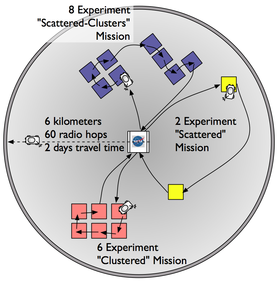
Figure 1: Diagram of circular crater with control center at the
middle. Examples of the three types of
missions are illustrated, with black lines showing order of experiments.
3.2 Faulty Sensors
Many of the experiments involve sensors that measure, scan, survey,
or otherwise acquire information about the environment. For each
sensor, NASA provides a range and accuracy specification, and a
probability of sensor failure. Thus the specification for a
thermometer might be:
range: -55C to +225C
accuracy: +/- 1.5C
failure probability: 0.07 per reading
The faults that cause sensor failures are transient, and when they
occur the sensor fails by producing a random output value, selected
uniformly from that sensor's specified range. When a sensor failure
occurs, there is no direct warning that the sensor result is bad.
The rover continues to function normally, and if it repeats the
experiment the probability of failure on next use of the same sensor
is completely independent of what happened on the previous use.
Even complex sensors such as cameras conform to this model. A
camera, for example, might, in addition to the data of the
photograph, return a measure of the variance of the picture density,
with a range of zero to 1.0, an accuracy of +/- 0.1 and a probability
of failure of .15 per photograph taken. Just as with the
thermometer, two photographs of the same scene taken at about the
same time would be expected to have the same density variance
measure, within the accuracy specification, and if the camera fails,
the density variance measure will have a random value within the
specified range.
NASA has asked you to design, as a part of your system, a technique
to detect bad sensor readings and thereby assure that no more than 5%
of the experimental results returned to Earth are victims of sensor
failure. It may be necessary for a rover to run some experiments
more than once to accomplish this goal.
3.3
Result
Sizes and Format
Missions are constructed such that the entire set of experimental
results from a mission requires about 600 megabytes of storage.
Thus,
each rover can store results from one entire mission, plus the results
from a few experiments from other missions. You may assume
that each experiment produces between 1 and 100 megabytes of data.
You will need to describe the
mission result format data
structure in your report. Remember that amendments can require
you to discard some already collected results, so you will need to show
how amendments are applied to your results data structure.
4. Mission Distributor
The mission distributor runs on the control center and is
responsible for handing missions out to rovers. You must
design this system, including a description of:
- Your approach for allocating missions to rovers.
Deploying additional rovers for a given mission may
improve your ability to tolerate faults or increase reliability.
- How you will deliver mission amendments. Bear in mind that
amendments can arrive at any time, after a mission has been
dispatched to a rover or even after a mission has been committed.
Consequently, some experiments deleted by an amendment are run anyway;
you must ensure that no experiments added by amendments before the
commit point fail to be
run. Because experiments are required to be run in a
particular order, when an amendment is received, all experiments following any added or
deleted experiment must be rerun. You will need to design
data structures for both the rovers and control center that track which
experiments still need to be run, given a set of
amendments and experimental results from fully or
partially executed missions. Missions may be amended multiple
times, and the probability that an amendment will arrive during any
period of time is independent of when an amendment was last received
(so there is no benefit to waiting to execute a mission until after an
amendment has been received.)
- The protocol used to communicate missions and amendments between
the control center and rovers or between pairs of rovers.
You may assume a mission can be described in a single radio
message. Make sure you describe how your protocol deals with the
possibility of transmission failure, including what it does about the
possibility of duplicates.
NASA will continue
uploading missions as long as there are still unfailed rovers. At
any
given time, however, there will be about 25
missions either waiting to
be
distributed or being executed. As
mission results are sent back to Earth, NASA engineers analyze the
experimental results and transmit new missions.
5. Mission Execution
You must also design the
software that executes the mission
plans on the rovers. Mission execution requires that the
rovers travel to each of the experimental execution sites, and carry
out the mission
experiments for each site. Experiments must be executed in
the order
specified in the mission, as they represent serial actions on the
planet's surface. As with travel time, the experiments in a
mission can take days to execute. You may wish to consider having
several rovers cooperate to complete a mission.
You may assume that rovers are
equipped with a high level API
for executing each of the experiments in the mission. These are
blocking function calls, such as:
procedure
takePanorama(startAngle, endAngle) returns
PanoramicPhoto
You will need to make sure to address the following issues:
- How does the control center detect that a rover has failed to
execute a mission? How does it respond to failures?
- How are mission amendments for currently executing missions
handled?
- How do you use mission type to help with mission execution,
if the additional information
about types is used at all?
- What data structure will you use for collecting experimental
results?
6. Result Collection
You will need to design the protocol for delivering experimental
results from mission execution between rovers and the control center,
or (if needed) for exchanging results between a pair of rovers.
This protocol
must be robust to failures in one (or both) of the rovers. You
should make it clear how your system assures that results from
completed experiments eventually reach the control center (even if the
rover carrying experimental results fails while running experiments,
while in transit, or while transferring results to the control
center). Make sure
you describe how your protocol deals with the possibility of
transmission errors, including what it does about the possibility of
duplicate messages generated by any retransmissions. Also,
describe how you will handle sensor faults.
Each experiment in a mission produces some results, which must be
delivered back to the control center (see Section 6 below.)
Experimental results for a single mission are not required to be
delivered together. If a mission is partially executed when a rover
fails, but the rover
has managed to offload results from some experiments before failing,
another rover may restart experiments from where the failed rover left
off (of course, that other rover must have to have some way of knowing
where it should restart.)
The control center will deliver results to Earth when the
Earth is visible from the control center. You do not need to
design this portion of the
system; you may assume that the control center has enough
bandwidth in a typical day to deliver all of the results stored in it
at a given time. Once results have been transmitted, they are
deleted from the memory of the control center.
Note that mission amendments will
not
arrive after the results for a mission have been offloaded to Earth. You
should make sure that your solution for applying amendments works for
committed missions, however, as amendments may arrive while mission
results are waiting to be sent to Earth.
7. Your Design
In this section, we discuss the critical aspects of your design that
you should be sure to cover in your writeup.
7.1 Design Goals
- The primary goal of your design should be to ensure that missions
uploaded to the control center are successfully executed
and the results will be delivered back to
the control center, despite failed rovers, including any amendments
made to missions.
- You should also try to mitigate faults and avoid repeating work
as much as possible,
as NASA
wants to be able to explore as much of the crater as it can before
all the rovers fail.
7.2 Issues to Address
In addition to the issues mentioned in Sections 4, 5, and 6, make sure
your report addresses the following additional topics:
- Does
your report clearly describe the following protocols
(using timing diagrams, pseudocode, and
English descriptions)? There may be others, but all
design projects should include:
- A protocol for distributing missions to rovers.
- A protocol for distributing amendments to rovers.
- A protocol for transferring experimental results from the rovers
to the control center.
- How do you name rovers for communication purposes (see Section
2.4)?
- How do your protocols for exchanging missions and experimental
results tolerate lossy communication? When can a rover delete
results for a particular experiment from its memory? Can results
be delivered multiple times? Can missions be executed multiple
times?
- How well does your approach continue to function as rovers fail
and their total number dwindles?
- When an amendment is applied to a partially completed
mission, how do you ensure that any parts of the mission following the
amended portions are redone?
- How does your approach assure that received messages actually
originated from another over or the control center (and not a Poodle
rover)?
Your report should describe an integrated system design that clearly
describes how you will address the three key problems (mission
distribution, mission execution, and result collection). Be
sure to describe your solution in enough detail that we can clearly see
that it will work. You may want to include:
- a diagram of the overall architecture of the system and its
decomposition into modules;
- pseudocode for appropriate algorithms (such as the algorithm for
allocating missions to rovers [see Section 4]);
- protocol
diagrams, as described above;
- data structures (e.g, for managing missions and amendments).
When possible, you should
rely on protocols or algorithms from the text or
papers rather than reproducing them in your report (but be sure to tell
us why they are appropriate). Finally, please refrain from extensive mathematical
modeling. It is fine to include back-of-the-envelope
calculations to justify a design decision, but (at most!) you should
need only simple algebra and basic probability theory.
8. Recommended Reading
In addition to concepts covered in 6.033 before Spring Break, this
project involves concepts from chapters 6, 7, and 8, some of which
you will not have covered in class before you begin working on this
project. Rather than reading all of the chapters before starting
your project, you may wish to use a different strategy: look up
unfamiliar terms in the indexes of those chapters and read just the
sections where they are defined or described. In addition, review
the glossary definitions of those terms. Also look at the
schedule of reading assignments and lecture topics to see when relevant
topics will be covered in class.
If particular, you may want to look up the following terms in the text:
Chapter 6:
|
sign, authentication |
Chapter
7:
|
fault tolerance design process,
forward error
correction, fault, failure, error, fail-vote, fail-fast, masking,
detectable error, mean time to failure, transient failure
|
Chapter
8:
|
commit point, undo, redo,
checkpoint, recoverability, idempotent, atomic
|
For additional background, see
this Wired.com article on how Mars
Opportunity and Spirit Rovers get data back to Earth:
http://www.wired.com/news/technology/0,1282,62409,00.html
9. Your written report
We now provide some suggestions on writing style and
outline the standard structure of a design report.
Suggestions on writing style
Who is the audience for this paper? Write for an audience consisting
of colleagues who took 6.033 five years ago. These are readers who
understand
the underlying system and network concepts and have a fair amount of
experience applying those principles, but they have not
thought carefully about the particular problem you are dealing
with. Assume that your paper will also be used to convince readers
that you have a feasible design. Finally, give enough detail that
your project can be turned over to an implementation team
with some confidence that you will not be surprised by the result. One
qualitative way that 6.033 reports are evaluated is by asking the
question, "Do we want this person on our team? Can this designer
provide us an accurate description of his/her design?"
Following are some tips on the organization of a design report. You
can find other helpful suggestions on writing this kind of report in
the 6.033 online lecture "How to Write Design Reports". You
may also want to look at the Mayfield
Handbook's explanation of IEEE documentation style. A good
book on writing style is:
"The Elements of Style,"
by William Strunk Jr. and E. B. White, Third Ed., MacMillan Publishing
Co., New York, NY, 1979. (Also available from the MIT libraries.)
Report Outline
Following is a suggested outline for your report. The full report
(including executive summary) should be no longer than 5000 words
(approximately 12 pages), single-spaced.
Executive Summary
Think of an executive summary as a long abstract. The executive
summary for DP2 should be no more than 1200 words (approximately 3
pages) in length. The executive summary is
a summary of the entire paper. It is not an outline of the
organization of the paper! It states the essential points of your
solution,
the rationale for your approach,
and a brief justification for your design. You may include a figure, if
appropriate, in your Executive Summary.
The Executive Summary is a stand alone document that is placed
BEFORE the title page. Because it is placed before the title page, your
name and title of your project should be placed on the Executive
Summary. The Executive Summary should be organized into enumerated
chunks and given descriptive headings. Do not staple the Executive
Summary to the report. Write the executive summary after you have
written your report.
Title Page
Give your design report a title that reflects the subject and scope of
your project. Include the names of your team members, recitation time
and section, and the date on the title page.
1.0 Design Overview
State the design purpose, list specific design considerations and then
briefly state your approach to each of those considerations. You may
assume that the reader has read the DP2 assignment; you do not need to
restate the problem in detail. In your Design Overview or early in your
Design Description, provide a figure of your design architecture. Your
Design Overview will probably be no longer than 1 or 2 paragraphs.
2.0 Design Description
Explain and elaborate your solution. A clear, detailed design
description is paramount to convincing readers that your design choices
are well-justified. Show how your solution satisfies the constraints
and solves design problems (or how it fails to do so). Explain how your
design choices are reasonable in the context of the problem statement.
Design descriptions also typically explain alternative approaches that
you considered and rejected, and why you rejected those approaches.
Finally, design description often include an analysis of the estimated
(or measured, if it applies) performance characteristics of your
solution.
You may need to use figures or pseudocode in this section. If you use
pseudocode to illustrate your solution, be sure to describe what the
pseudocode does in English as well. The Design Description should
be chunked into sections with subheadings and organized by design
function or system module.
3.0 Conclusion
Evaluate your design in the Conclusion. Summarize design problems you
solved,identify problems in your design, and justify why your design
does not address these problems.
References
Document your sources, giving a list of all references (including
personal communications). The style of your citations (references) and
bibliography should be in IEEE format.
How do we evaluate your report?
Your report will be evaluated for content and writing fluency.
Some content considerations:
- Is the design described unambiguously?
- Does the design achieve design goals?
- Are your design decisions well justified?
- Do you fulfill all the design requirements?
Some writing considerations:
- Is the report well-organized within and across sections?
- Is it professionally presented?
- Are text and figures integrated?
- Is the writing clear?
Collaboration
On this project, you will work in teams of 3 students. Send your
list of team members to your recitation instructor via email by
11:59 PM on April 5.
Tasks and Due Dates
- Design proposal (800 words or less, approx. 2 pages). Due: April
13, 2004.
This should be a concise summary of your design choices and of the
overall system design. Also, if any of your design decisions are
"unusual" (particularly creative, experimental, or risky, or
specifically warned against in the assignment), it would be wise to
describe them here.
- Executive summary (1200 words or less, approx. 3 pages). Due:
May 6, 2004.
The executive summary should be submitted with your full report.
- Detailed technical report (5000 words or less, approx. 12
pages). Due: May 6, 2004.
The first three pages of your report include your executive summary.
That is, the total number of pages should be 3+9 = 12, not 3+12
= 15.
- a presentation on May 11th (details will be given as the date
approaches).
Please use 1-inch margins and use single-sided printing. Include
your name on
each page of your report (the footer is a good place to add your name).
Remember to use diagrams where appropriate.