You will do design project 2 in teams of three students who are in your recitation or share the same instructor. There are four deliverables for Design Project 2:
A list of team members emailed to your recitation instructor by April 10, 2008.
One copy of a design proposal not exceeding 1200 words, due on Thursday, April 24, 2008.
One copy of a design report not exceeding 5,000 words, due on Thursday, May 8, 2008.
An in-class presentation on May 13, 2008. While this presentation falls during the last week of classes, in consultation with the chair of the faculty we have determined that the assignment falls in the spirit of the end-of-term rules.
6.033 design reports are different from quizzes and problem sets. These projects, like those in real life, are under-specified, and it is your job to complete the specification sensibly, given the project requirements. As with real-world designs, those requirements often need some adjustment as you flesh out your design. We strongly recommend that you start early so that you can iterate your design. A good design will likely take more than a few days.
Today, the most common home network configuration is an off-the-shelf wireless access point / NAT router connected to a broadband Internet connection such as DSL or cable modem. In this type of configuration, the bottleneck in the system is the DSL link. The nominal capacity of typical wireless access points is 54 Mbit/sec, while the capacity of a low-end DSL line is typically about 1 Mbit/sec.
Wireless is a shared medium that is similar in many ways to a shared Ethernet bus. A WiFi Access Point (AP) is like an Ethernet switch, in that it enables multiple clients (hosts with WiFi cards) to communicate and share the medium. In addition, APs typically also behave like routers and network address translators (NATs). Each client that associates to an AP will be assigned an IP address from that AP’s pool of DHCP addresses. This address is not a routable Internet address, but rather is assigned from a private address space. The AP will then use NAT to translate ports on these private addresses to and from ports on the single routable IP address assigned by the ISP who provides the DSL service.
Thus, during normal operation the AP will receive packets on the wireless medium from one or more clients, and will put them in a queue to be processed by NAT and forwarded to the DSL link. Likewise, packets received from the DSL line will be queued, processed by NAT, and transmitted to the appropriate client via the wireless medium.
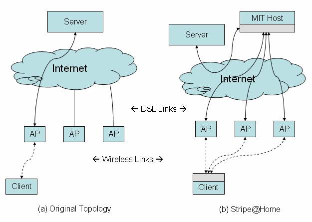
You observe that several of your neighbors have independent DSL or cable subscriptions and wireless APs, but typically they are not all using them at the same time. Thus, in principle you and your neighbors can benefit from cooperating to spread load across your DSL links, using the wireless medium to send traffic via each other’s APs. For example, by spreading a single transfer over 3 DSL lines as shown in Figure 1, it should be possible to achieve an aggregate transfer rate of 3 Mbit/sec, with comparable latency to using a single link.
Figure 1: General architecture of Stripe@Home, with your design components shown in gray. For clarity, only one client and server is shown, but your design should support many concurrent clients, each connecting to many different servers.
The goal of Stripe@Home is to design a system that allows clients to associate to multiple APs concurrently, and to “stripe” the data in their TCP connections via several APs. This “striping” operation must be transparent to both the client and the server of the end-to-end connection. Thus, if you were to download a large file from the web, different parts of the file would be downloaded over different DSL lines, but from the perspective of the web server or browser, it would look exactly the same as before.
Having heard that you did well in 6.033, your neighbors agree to be beta-testers for your new link-sharing system. Following your instructions, they reconfigure their access points to all use the same channel (e.g. channel 11), and modify their security policy to allow you access to their networks, so that you can begin to develop the system. Your lab at MIT also allows you to install a server machine on the MIT campus for use in this project.
In this section we explain the basic requirements for the design of Stripe@Home, describe assumptions, and propose several analyses to perform. Figure 1(b) shows the basic architecture of Stripe@Home. Your design will insert components in the areas marked gray in the diagram.
Figure 1 shows the path of a connection from the client to a server, before and after the implementation of Stripe@Home. Before Stripe@Home, a client sends packets via its access point, over the DSL line, and directly to a destination server via the Internet. After installing Stripe@Home, the client’s machine now splits the traffic up into N separate streams, each of which is sent via a different access point and DSL line. These streams are merged together again at a helper server (“MIT Host”), and the reconstituted stream is forwarded on to the destination server. Data returning from the server follows the reverse path back to the client; it is split up at the helper server and merged back together at the client. Your design must meet the following requirements:
TCP Striping: Your design should stripe data in TCP connections. Other protocols (e.g. UDP, ICMP) may be striped at your option, but must in any case be transmitted to their destination.
Transparency: Your design should be completely transparent to TCP applications, in both directions. Using your system, it should be possible to use a standard, unmodified web browser on the client laptop to connect to an unmodified web server on the Internet. Everything must appear exactly the same to client and server, even though the data might be striped over several DSL links. In particular, TCP connections through your system must deliver the correct data, reliably and in order. There is also a looser requirement that they “behave like” TCP streams, in other words that you would reasonably expect applications to behave similarly whether connecting directly or using Stripe@Home.
Throughput: Your system should yield increased throughput both to and from the server. For example, your client’s throughput should approach the sum of the capacities of the intervening DSL links when no other clients are active. If some links have more capacity than others, your system should be able to allocate more of the flow to those links. Your system should dynamically respond to changes in link capacity.
Latency: The latency experienced by clients should be comparable to that of a normal connection – not too much worse. In particular, clients should be able to use interactive sessions such as SSH sessions or AJAX applications, without noticeable increases in latency.
Support for multiple clients: Your system should support 5-10 users (e.g. you and your neighbors) concurrently, and support several connections from each user. Your system should strive to divide available capacity equally among all Stripe@Home connections.
Adaptation to AP Connectivity: Your design should dynamically adapt to use new APs as they are discovered, and to discontinue use of APs that fail. During an AP failure, a transient reduction in performance is acceptable, but the system should recover within 10 seconds as long as there is at least one active link remaining.
NATs: Stripe@Home should work through NATs, since all of your neighbors’ APs also act as NAT devices.
Because this system is fairly complex, it may be helpful to try to tackle the design problem incrementally. In this section we propose a series of stages which may help you think about the problem. This is only a suggestion – feel free to use any strategy you prefer. Note also, that ultimately in your report we want you to describe and analyze a single integrated design.
1. Single Client, Multiple APs: First, just as in Figure 1, assume a single client (e.g. your laptop) and assume that all DSL links have the same capacity. Devise a way to intercept a client connection and transparently stripe it over multiple APs. The key challenge here is to ensure that Stripe@Home is transparent to the client and server, apart from perhaps having a slightly higher latency.
2. Supporting Multiple Clients: Next, extend your design to handle multiple clients. The key challenges here are addressing the fact that your neighbors’ routers are also NATs, and that the MIT host has a single IP address. How does traffic returning from the destination server get back to the correct client?
3. Load Balancing and Recovery from AP Failure: Now assume that different broadband connections vary in speed and loading. For example, the nominal capacity of a FiOS connection might be 6 Mbit/sec where a low end DSL is 1 Mbit/sec. In addition, the load on the connections will change dynamically as different clients use the system at different times. Observe that, if your system divides the traffic evenly among the connections (e.g. distributing segments of data “round robin”), it will only achieve a throughput of N times the slowest link. Design a load-balancing mechanism that dynamically adjusts the proportion of traffic sent via each connection in both directions, and adapts to AP failures and to new APs coming on line.
1. You can assume that you may install a helper server machine on the MIT campus. This server has unlimited CPU and network resources, and a gigabit Ethernet interface named “eth0”.
2. Assume that all wireless clients run the same O/S, and each has a 54 Mbit 802.11 interface named “ath0”. Assume that the wireless link from the client is lossless, and the client has unlimited CPU.
3. You may use the packages and APIs described in section IV to modify the behavior of the network stack on the client machine and on the helper server on campus. You may NOT modify the client software (e.g. web browser), destination servers, or AP firmware.
4. You may disregard memory size and CPU costs in all cases.
1. Assume that different Internet access links nominally operate at different speeds, and their speeds change dynamically with load. In all cases, assume that the Internet access link is the bottleneck link end-to-end.
2. You may assume that end hosts have small socket buffers, and the maximum latency of a packet through the Internet is 500 ms. Assume the MTU through the Internet is 1500 bytes.
3. You need only be concerned with connections initiated FROM your laptop TO a server on the Internet; assume that you do not use any applications that require your laptop to operate a server. Since each AP also acts as a NAT, exposing servers would require special configuration of the AP hardware.
4. There are no malicious or greedy clients.
In the analysis section of your report, address the following points:
1. Characterize your load-balancing algorithm for non-uniform link capacities. As an example, analyze your system assuming three DSL lines, of 6 Mbit/sec, 2 Mbit/sec and 0.5 Mbit/sec. Estimate the steady-state throughput of your system as well as the approximate time required to reach steady-state. If your design leads conveniently to a more general analysis, such as a bound on the expected reordering latency, provide any such characterizations.
2. Suppose that you have set up a 5 AP Stripe@Home system consisting of five 1 Mbit DSL links, and you are using your system to perform a large download over TCP. How will competing traffic from your neighbor impact your client’s throughput? How quickly do you expect your rate will stabilize? In your answer consider the following two cases: (a) one of your neighbors is not using your system, and begins a large TCP download over just their own DSL, and (b) one of your neighbors is using your system, and begins a large striped download over the same set of 5 APs.
3. What is the impact on your system if an AP should fail? Assuming a 5 AP system with 1 Mbit DSL links, how will AP failure impact your client’s throughput? How long will it take to detect the failure? How long will your system take to stabilize? What happens if the DSL fails but the AP remains up? How does your system recover from data lost when an AP or DSL fails?
4. Are there any cases in which a direct TCP transfer would have succeeded, but your system in the middle causes it to break? Note that these issues may not be something we expect you to fix – just describe. For example, if the MIT Host reboots, current connections might be lost, and there may be no way around this. Are there any cases where the “direct” version would fail, but your system does not?
To simplify the design process, we provide several helpful packages with APIs, that you can use in your design. Don't worry if you don't end up using them all! Different design strategies will use different subsets of the functionality that we've provided. Note, that you may modify these APIs to expose additional information if you find it strictly necessary for the correctness of your design. However, you must carefully justify any such proposed changes in your design report.
As a rule, WiFi cards can only associate (i.e. register to send and receive traffic) with one AP at a time. However, to stripe data across several DSLs, each behind its own AP, we will need to find a way to send via several different APs nearly concurrently, and thus need a way to concurrently maintain multiple associations. Fortunately, you have found a package that allows you to associate to several APs concurrently. The package provides a simple API with two calls:
  list<APID> WifiScan()
  String WifiAssociate(APID)
The package works as follows. WifiScan() reports the IDs of all access points that are currently accessible via the WiFi interface card, and have good link quality. The output of WifiScan() is similar to the information displayed when selecting an AP to connect from your laptop.
WifiAssociate() takes the ID of a specific AP, configures the WiFi interface card to associate to that AP (in addition to any others previously associated), and dynamically creates a virtual network interface “virt:APID” to represent data traffic to and from that specific AP, where APID is the MAC address of the AP. The name of the new interface is returned as a string. These interface names can be referenced from the API described in section IV.2.b.
Because the virtual interface names include the AP's ID, they will define a consistent mapping. Thus, in the event that WifiAssociate() is called with an APID for which an interface already exists, it will simply return the existing interface. Interfaces are garbage collected when the AP has de-associated (e.g. if it is out of range, it is turned off, or otherwise fails). Any socket currently using that interface will close and return an error from the next socket call.
An example using this API:
  String X = WifiAssociate("00:00:23:45:56:23");
  // X is a new virtual interface, "virt:00:00:23:45:56:23"
  // associated to "00:00:23:45:56:23"
  String Y = WifiAssociate("00:00:33:33:66:66");
  // Y is a new virtual interface, "virt:00:00:33:33:66:66"
  // associated to "00:00:33:33:66:66"
  String Z = WifiAssociate("00:00:23:45:56:23");
// Z reports existing "virt:00:00:23:45:56:23" interfaceAn I/O interface can implement either blocking or non-blocking semantics. In blocking, or synchronous semantics, each I/O call suspends execution of the calling thread until the requested operation completes. If for some reason the operation cannot be completed immediately, the calling thread will be suspended until the operation can be completed; for example, if a read is requested but no data is available, the calling thread will block until data arrives to fulfill the read. This approach works well for sequential I/O operations, but requires that concurrent I/O operations be implemented using a multi-threaded design. Such designs often end up being more complex and error prone because of the additional need to synchronize access to shared variables from multiple threads.
In contrast, non-blocking semantics allows the implementation to reside in a single thread of execution, eliminating any possibility of thread-related problems such as race conditions or deadlock. In a non-blocking, or asynchronous semantics, an I/O call is required to perform only the operations that can be done immediately, after which control is returned to the caller. Since the requested operation may not always complete, a non-blocking API must include a way to indicate to what extent the operation completed.
For the purposes of using TCP stream sockets in your design, you may use the following non-blocking API. All of these calls are guaranteed to return immediately to the caller. In the event that a Accept(), Read() or Write() call cannot complete immediately, an exception is thrown. (Note: see section IV.2.b for an explanation of the NoInterface exception.)
  Socket Connect(IPAddr, Port) Throws ConnFailed
  Socket Accept(Port) Throws NotReady
  String Socket.Read(length) Throws EOF,NotReady,NoInterface
  Socket.Write(String) Throws EOF,NotReady,NoInterface
  Socket.Close()
  IPAddr Socket.GetPeerAddr()
  Port Socket.GetPeerPort()
Both Connect() and Accept() return new TCP stream sockets. (Note: These functions are a simplification of the standard socket interface).
Connect() initiates a client TCP connection to the specified port and address, and returns a socket representing the new connection. If the connection to the destination host cannot be established, it immediately throws ConnFailed.
Accept() is invoked by a server to check to see if a client is waiting to connect. If a client is waiting, Accept() will return a socket representing a connection to the new client. The accessor functions GetPeerAddr() and GetPeerPort() return the address and port of the connected peer. If no client is currently waiting, a NotReady exception is thrown.
The Read() method implements non-blocking all-or-nothing read from the socket. In the event that end-of-file is reached (i.e. the socket closed), the final Read() may return less than the requested number of bytes. After end-of-file is reached on a socket, further Read() calls throw an EOF exception. NotReady is thrown if the amount of data waiting to be read is insufficient to fulfill the requested read.
The Write() method implements non-blocking all-or-nothing write to the socket. Write will throw an EOF exception if it is called after end-of-file is reached for writing (i.e. if the TCP peer closed its input). NotReady is thrown if space in the write buffer is insufficient to accept the requested write.
Non-blocking designs are typically organized as an event loop. In an event loop, a thread runs in an infinite loop, checking the current conditions of a set of I/O channels, and subsequently taking actions based on prior state and the current conditions. For your design, we don’t want you to write code – but we do want you to explain how your event loop will process I/O events. The following example expresses an event loop that accepts client connections, reads the data from them, and prints out their contents. Note that in this exception handling syntax, “excepting X try {Y}” is shorthand for “try {Y} catch X {}”.
  forever do {
    excepting NotReady try {
      s = Accept(8001);
      add s to the list of client sockets.
    }
    for each socket s in the list of client sockets {
      excepting NotReady try {
        data = s.Read(4096);
        print("From client "+s.GetPeerAddr()+" port "+s.GetPeerPort()+" got "+data);
      }
      catch EOF,NoInterface {
        s.Close();
        remove s from list of client sockets.
      }
    }
  }
In your explanation you may find it helpful to break down the event loop into different sections, each of which handles one class of I/O sockets, or that handles all sockets related to a particular client, as long as these subsections can all be called from a single master event loop. This type of modularity may make your design much easier to explain and understand.
Note: do not worry about the overhead of “spinning” while checking I/O. A real implementation would use “select()” to block while no I/O is ready, but you should ignore this detail.
Machines that support IP networking often have multiple network interfaces. For example, many laptops have both wired and wireless network interfaces, and under some conditions, both interfaces might be in use concurrently. Each network interface will have an IP address associated with it, and entries in the routing table indicate which interface or gateway will receive the packet next, based on the destination address in the header.
For most end-hosts, one route is the “default route”. All packets that are not covered by a more specific table entry – destinations in the “rest” of the Internet – will be routed according to the “default route” entry. However, some hosts are “multi-homed”, meaning that they have two different ways to reach the “rest” of the network.
In our system, we want to stripe traffic bound for the Internet across the separate DSL lines that are reachable by our system. Thus, the system we are designing is “multi-homed”, and the choice of route to the Internet is not determined uniquely by the destination. This means that we can't use the routing table alone to control the routing behavior: we must rely on another method. In this section we extend the sockets API with an additional call to force a socket to use a specific interface:
Socket ConnectVia(Interface, DestIPAddr, DestPort) Throws ConnFailed,NoInterface
Like Connect(), ConnectVia() initiates a client TCP connection to the destination address. But whereas Connect() will route the traffic making up the connection according to the destination address and the kernel routing table, ConnectVia() will force its traffic to be routed via the specified interface. This allows a multi-homed host to select a specific route to use, in cases where the routing table would not impose any specific preference. The interface parameter specifies the string name of the interface, e.g. “ath0” or “virt:APID”. ConnectVia() throws exceptions if the connection cannot be established or if the interface does not exist.
Note that if a socket is bound in this way to a particular interface, and that interface is subsequently removed from the system, the next method on that socket will throw a NoInterface exception. This will happen if an AP de-associates while a socket is connected through it.
Thus far we have only discussed TCP stream sockets. Some designs may want to instead send and receive UDP datagrams. The following API extends support for datagram sockets:
  Socket BindVia(Interface, SrcPort) Throws NoInterface
  <IPAddr,Port,String> Socket.RecvFrom() Throws NoInterface,EOF,NotReady
  Socket.SendTo(IPAddr, Port, String) Throws NoInterface,EOF,NotReady
BindVia() serves a similar purpose to ConnectVia(), but establishes a datagram socket rather than a stream socket, bound to a specific port on a specific interface. Datagrams received at that port will be delivered via the RecvFrom() method of the socket, and the SendTo() method can be used to send a datagram. RecvFrom() also reports the address of the peer that sent the datagram.
In order to transparently redirect and stripe the data in TCP connections from our client to a server on the Internet, we need some way to gain access to network traffic from within the network stack. We provide two different ways to achieve this, which capture data from different points in the stack. The TCP Intercept API captures the data stream at the transport layer, presenting the byte stream to your application via a socket interface. The IP Packet Intercept/Inject API captures the data stream at the IP layer, presenting the sequence of IP packets directly. In your design, you may choose to intercept traffic at the IP or transport layer.
Figure 2: Using the TCP Intercept API. The client calls Connect(18.26.1.2,8001), but the connection is intercepted at the TCP level and processed by the Split-TCP application, when then makes its own connection to the destination server.
One way to redirect and stripe the data in client-initiated TCP connections is to intercept the TCP connections initiated by a local client and destined for a host on the Internet, as shown in Figure 2. The TCP Intercept API provides a way to implement what is known as “split TCP”. In split TCP, an intermediary acts as a TCP endpoint not only for streams that are addressed to it, but also for streams addressed to some other host on the Internet. This intermediary intercepts and acks data addressed to the true destination host, initiates its own connection to the final destination, and subsequently passes the data stream along.
Split TCP is often used in practice to decouple two parts of a network that have very different properties, e.g. in terms of latency or loss. A major disadvantage of this approach is that it loses the end-to-end reliability provided by end-to-end TCP.
The TCP Intercept API provides two additional calls:
  <Socket,DestIP,DestPort> AcceptIntercepted(interface) Throws NotReady,NoInterface
  Socket.Release() Throws PermissionDenied
The AcceptIntercepted() function is semantically similar to the Accept() function. When a client attempts to establish a new TCP connection, the system intercepts it and makes it accessible to the AcceptIntercepted() call. When called, if no intercepted sockets are waiting, NotReady is thrown. If an intercept is waiting, a new socket is returned along with the intended destination address and port.
Based on the intended destination, you might prefer to un-intercept the connection and let it through unmodified. This can be done by invoking the Release() method on the socket. If Release() is called after using the socket (e.g. calling Read() or Write()), the connection cannot be un-intercepted, and it will throw PermissionDenied.
Figure 3. Using the IP Packet Intercept/Inject API. The client calls Connect(18.26.1.2,8001), but the connection is intercepted at the IP level and processed before being sent on its way to the destination server.
Another way to redirect and stripe traffic, shown in Figure 3, involves intercepting the IP packets that the client addresses to hosts on the Internet, making modifications to their content, and later injecting them into the network again, perhaps at different location. To support this approach you can use a Packet Intercept/Inject API. Note that this interface deals with IP packets as they appear in the network, as opposed to the data stream that is delivered by a TCP socket.
  Socket InterceptHostToNet(interface) Throws NoInterface
  Socket InterceptNetToHost(interface) Throws NoInterface
  String Socket.Intercept() Throws NoInterface,NotReady
  Socket.Inject(String) Throws NoInterface,NotReady
The InterceptHostToNet() and InterceptNetToHost() functions return a socket that intercepts IP packets on the specified interface. InterceptHostToNet() intercepts packets sent from the host on the specified interface, and injects to the net on the specified interface. InterceptNetToHost() runs the other direction; it intercepts packets sent from the net on the specified interface, and injects to the host.
These sockets support two special methods: Intercept() and Inject(). If an intercepted packet is waiting, Intercept() returns that packet as a string containing the complete text of the packet, i.e. the IP header, any transport headers, and payloads; otherwise it throws a NotReady exception. If there is buffer space available, Inject() injects the specified packet; otherwise it throws NotReady. In the event that the interface does not exist (e.g. if the underlying AP has de-associated), these functions throw a NoInterface exception.
For example,
  Socket sock = InterceptHostToNet("ath0")
  String pbuff
  set pbuff to empty
  forever do {
    if pbuff is empty then {
      excepting NotReady try {
        pbuff = sock.Capture()
        print(pbuff)
      }
      catch NoInterface {
        quit because we lost our interface
      }
    }
    excepting NoInterface,NotReady try {
      sock.Inject(pbuff)
      set pbuff to empty
    }
  }
will print out all traffic sent through the “ath0” interface, and pass it along unchanged.
If you decide to use the Packet Capture API, be sure to provide a clear explanation of the structure of the packets you are capturing or injecting, and in particular describe in detail any changes you make to these packets as they travel through your system.
The design proposal should be a concise summary (1200 words) of your overall system design. It's a good idea to start out with a system diagram to show how you plan to make the overall system work. Your proposal should lay out the basic mechanisms that allow you to capture and stripe client connections.
You do not have to present a detailed rationale or analysis in your proposal. However, if any of your design decisions is unusual (particularly creative, experimental, risky, or specifically warned against in the assignment), or you want to change any of the assumptions substantially, it would be wise to describe such changes in your proposal.
You will receive feedback from your TA in time to adjust your final report.
Here are some items we are interested in seeing in your final report.
System diagrams: One or more high-level diagrams that show the different components, how they interact, and some detail about the components. Show how your system intercepts client data, stripes it over multiple access points, and routes returning data back to the appropriate client.
Algorithm description: You should clearly explain how the algorithms in your design work. In particular, explain how you achieve the following design requirements:
Reliability: Explain how your system ensures that the TCP stream is transferred reliably.
Failure detection and recovery: Explain how your system detects and recovers from failure.
Load balancing: Explain how your load balancing scheme works.
Layering: If your design can be decomposed into layers, explain how it is layered, and describe the mechanisms, packet formats and protocols at each layer.
Packet/Session Trace: Explain how data flows from the client to the server and back, showing how it traverses your system and what protocol decisions are made each step of the way.
Analysis: Characterize the performance of your system, according to the guidelines in Section III.4.
Note that your report should describe only the final design of your system, even if you followed the suggested incremental design process.
Do not write your design in code. Precise API specifications are provided to clearly define what interfaces are available for interfacing to the network, and to provide a way to clearly express how you intend to interleave your I/O operations in order to achieve the design goals. You may include pseudo-code if you wish, however it must not take the place of a clear explanation of your algorithms in the text of your report. In particular, your text must explain how it works and why – the principles and rationale of the design.
The best approach for writing up your design is to define a main event loop that invokes a set of modules each time through the loop. These modules are state machines, each handling a part of the data path. Breaking it down this way will make it easier to express the system in modules, rather than one monolithic loop.
The following are some tips on writing your design report. While the Writing Program will not be grading DP2, you can still use them as a valuable writing resource.
Audience: You may assume that the reader has read the DP2 assignment but has not thought carefully about this particular design problem. Give enough detail that your project can be turned over successfully to an implementation team.
Report Outline (use this organization for your report):
Title Page: Give your design report a title that reflects the subject and scope of your project. Include your names, email address, recitation instructor, section time, and the date on the title page.
No Table of Contents.
Introduction: Summarize the salient aspects of your design, the trade-offs you made, a brief rationale for the design you have chosen, and the results from your analysis.
Design Description and Analysis: Explain and elaborate your solution. Show how your solution satisfies the design constraints and solves the design problem (or how it fails to do so). Be sure to identify trade-offs you made, and justify them. Clearly describe your analysis and the conclusions you have drawn from your analysis. You will want to sub-divide this section into subsections and use figures or code, where needed, to support your design choices.
Conclusion: Provide a short conclusion that provides recommendations for further actions and a list of issues that must be resolved before the design can be implemented.
Acknowledgments and References: Give credit to individuals whom you consulted in developing your design. Reference any sources cited in your report. The style of your references should be in the format described in the Mayfield Handbook's explanation of the IEEE style.
Word count. Please indicate the word count of your document at the end of the project.
When evaluating your report, your recitation instructor will look at both content and writing and assign a letter grade. We assess each one of these components according to the following criteria. The criteria are listed in order of importance.
Clarity. Is the design described well enough to be evaluated and implemented? Can the reader understand your analysis? If we cannot understand your design and analysis, we cannot fully assess the other criteria.
Correctness and completeness. Your solution should meet the requirements specified in section III.
The following links provide good background on IP, NAT, and IP tunneling.