6.033 Spring 2014 Design Project 2: Running Jobs in a Data Center Network
Due Dates and Deliverables
There are four deliverables for Design Project 2:- A list of team members emailed to your TA by April 16, 2014.
- A presentation rehearsal scheduled on May 2, 2014.
- One copy of a design report not exceeding 5,000 words, due at 5pm on May 9, 2014.
- A five-minute in-recitation presentation, on May 13 or May 15, 2014.
Late submission grading policy: If you submit your DP2 report late, we will penalize you one letter grade per 48 hours, starting from 5pm on the submission day. For example, if you submit the report anywhere from 1 minute to 48 hours late, and your report would have otherwise received a grade of "A", you will receive a "B"; if you submitted 49 hours late, you would receive a "C".
You must work in teams of three for this project. All three people on a team must have the same recitation instructor (you may team up with people from either of your instructor's sections).
Introduction
Over the past few years, it has become common to run large computation tasks in public data centers. A user may pay Amazon, Rackspace, or other data center providers in return for using their computing facility. The user divides the desired computation into smaller jobs and embeds each job in a virtual machine (VM). The virtual machines get deployed on the various physical machines in the data center. The VMs of a particular user communicate with each other over the data center's network to collaborate on delivering the desired computation task. At any point in time, multiple users run their computations in the data center. Each user pays the data center provider a fee that depends on the number and duration of the used virtual machines.You are a user of public data center. Your objective is to complete a desired computation that involves a number of VMs in the shortest possible time. Your design has to take into account that you share the data center with other users with unknown and time-varying demands.
Data Center Networks
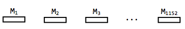
In this section, we describe the data center network. You may assume that the network is known to your system.Data center networks typically organize their networks in a hierarchical way. In particular, the data center where you will run your VMs has 1,152 machines. Each physical machine has a unique ID. (Because the network is so large, we won't show every single machine in each image.)
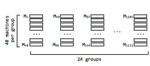
These machines are divided into groups of 48 (i.e., there are 24 groups). A machine has an extremely fast network connection to every other machine in its group.
So that the groups can communicate with one another, we connect each group to its own router. Each of these "group routers" is connected to two "aggregate routers". There are eight total aggregate routers.
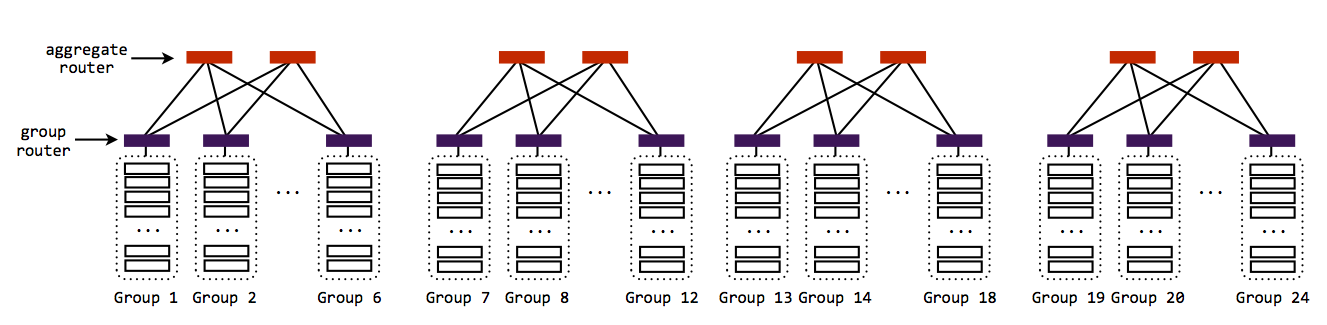
Because of the way the group routers are connected to the aggregate routers, the entire network is still not connected. Instead, there are four clusters of six groups each, and every group in each cluster is connected to the same two aggregate routers. This means that every machine in a cluster can communicate, but that there aren't any links across clusters.
To complete the network, each aggregate router is connected to two "core routers". There are only two core routers.
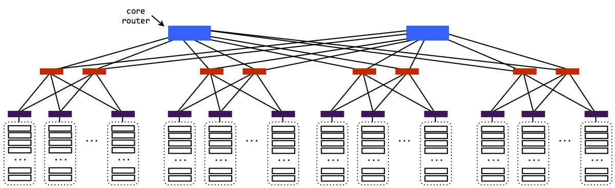
Now there is a path from every machine to every other machine.
You should be able to tell from the description of this network that sometimes, two pairs of communicating machines will need to share links, and other times they won't. For example:
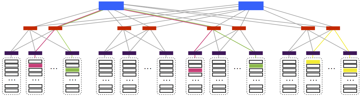
In the above picture, the pink and green pairs share some links between aggregate and core layers. They share no links with the yellow pair.
Because the number of routers decreases in each level of the network, the links close to the core routers will be used a lot, by lots of different connections.
Virtual Machines
As a user of this data center network, you do not actually get access to the individual physical machines. Instead, you use virtual machines (VMs). Similar to the way threads allow multiple programs to utilize the same processor, virtual machines allow multiple users to use the same physical machine. Virtual machines give users the illusion that they are using a full physical machine; in reality, the physical machine is home to many different virtual machines. (For a more detailed explanation of virtual machines, see Section 5.8 of your textbook.) In this data center, each physical machine can host 4 virtual machines. These 4 VMs may belong to the same user or different users.Link Capacity
In this data center, all links have the same capacity (e.g., 10 Gb/s).Routing
While the network has multiple potential routes between any pair of machines, you should assume that the underlying routing protocol will pick a single route between any pair of nodes. You do not need to worry about routing.The Problem
As a user of the data center, whatever application you are running will use multiple virtual machines. These virtual machines can be located anywhere on the network; this is referred to as a placement of virtual machines on the network. For example: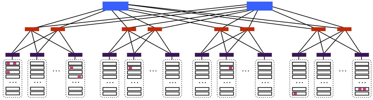
In this picture, each pink box is a virtual machine (there are ten pink boxes). Some of the virtual machines are very far apart in the network, and others are very close (there are even a few that share the same physical machine). Even though you, as a user of these virtual machines, would have the illusion that your virtual machines were each directly connected to one another, the paths between some of them traverse multiple links in the network.
If your application has to transfer a large amount of data, the condition of the paths between the virtual machines will affect its performance. A large transfer that goes over a very slow path can cause the entire application to run slowly.
A connection between two virtual machines will be slow if many other connections are also using the same path. In the data center network, this might happen because traffic from other users is sharing the same path(s) that your traffic is using. However, as a user of the data center, you have no information about any other user. This means that you are not told how much other traffic is on a path or how long that traffic will last.
Your Job
Your job is to build a system that, given the VMs of a user and their communication needs, it places these VMs on the data center network in a manner that minimizes the time until the completion of the application. Your system should adapt the placement of the VMs in realtime to cope with changes in the network due to the arrival of new users or the completion of existing applications.Your system is given two pieces of information:
-
n, the number of VMs the application uses. -
B, annxnmatrix that specifies the number of bytes that each pair of VMs will transfer.
For example, in an application with three VMs, where VM0 transfers 10MB to VM1, VM1 transfers 2MB to VM0, and VM1 transfers 3MB to VM2, B will look like this:
B = [ 0         10,000,000 0         ]

       [ 2,000,000  0          3,000,000 ]

       [ 0         0          0         ]
Notice from this example that:- B may not be symmetric; VMi may transfer a different number of bytes to VMj than VMj transferred to it.
- The entries on the diagonal will always be zero, as they represent the number of bytes a VM transfers to itself.
- While the total amount of traffic from VMi to VMj is known and described in the matrix B, the data is generated by VMi in realtime. Hence, there are instances in time when VMi may have no data to transmit, but the transfer is not yet complete.
- The VMs communicate using TCP. You can assume that each pair of VMs communicate with only one TCP connection. You need not worry about establishing these TCP connections or the details of the user application.
n VMs in the
data center network so that the application completes quickly. As
mentioned above, you should not assume that these VMs are the only
ones running on the network; there may be other VMs from other users,
about which you know nothing. As a result, the conditions of the
network can change as the application is running.
Your job is to optimize the inter-VM communication time. You can assume that the CPU and memory resources available to each VM are the same regardless of the physical machine on which the VM runs. You can also assume the propagation time in our data center network is negligible.
System Design
At a high level, your system will have two components: a measurement component, and a placement component. The measurement component will take care of measuring the network conditions in the data center. The placement component will determine how to place the virtual machines given the measured conditions.Measurement Component
The goal of the measurement component is to learn the properties of the paths between the VMs. In designing the measurement component, think about the following four issues:- What quantities to measure.
- How to measure these quantities, including whether it is possible to get an accurate value, or whether you will need to infer this value (e.g., if you wanted to measure instantaneous queue length in the routers, could you?).
- How often to measure these quantities.
- How much traffic your measurements are consuming.
- Available bandwidth (the amount of bandwidth available on the path); i.e., the bottleneck capacity minus the bottleneck traffic.
- Your application's own throughput
- Packet loss rate
Once you decide what to measure, you need to describe the measurement process. Note that your measurement code has to run in your VMs. You cannot run code on the routers or on machines that do not host your VMs.
The data center network is very large. With only
n
virtual machines launched, it may be difficult to get a sense of what
the rest of the network looks like. For that reason, you may choose
to launch additional virtual machines (beyond n). Note
however that the user pays for each VM (e.g., 10 cents per minute per
VM). Hence the system should balance the cost of deploying additional
VMs (beyond the n required by the application) with the
saving that may result from the discovery of better paths.
Also note the tradeoff between exploration and exploitation: You may decide to move one of the
n VM to a new machine
to explore a potential path. The new path may be worse or better than
the current path, but you would not know until you measure it.
Placement Component
Given the matrixB mentioned earlier, as well as the
network measurements your measurement component performs, your system
will need to place the virtual machines on the network such that the
application finishes as fast as possible, within reason.
In designing the placement component, and its interactions with the measurement component, think about the following four things:
- What components of your system do the measurement, and what components do the placement? Where does the placement component run? Is everything distributed? Are some components centralized? Etc.
- Once the measurement is done, how is it communicated to the placement components? How can the placement component proceed if the measurement component (or some portion of it) doesn't respond?
- How does the placement component actually make its placement decision (i.e., given the measurements and the communication requirements, where do you place the VMs)?
- How will your placement strategy interact with the placements of other users? Remember that you are not the only user of this system. For instance, if your strategy was to place all of your virtual machines on the same physical machine, keep in mind that you may be unable to find a physical machine with enough free space, since the network is hosting many other virtual machines from other users. Similarly you cannot assume that you can place all of your VMs on machines in the same group. Your system should be able to work well even in the presence of many other users. It should also adapt as new users join and old applications complete.
Regarding the fourth point, keep in mind that other users will also be placing machines. If your system tries to place a virtual machine on a particular physical machine and cannot, it should be able to recover (the
place API call, detailed below, will indicate
whether a VM was successfully placed, and the
related random_place function is guaranteed to place a
machine).
Even after you find a good placement and place the VMs accordingly, the network conditions keep changing due to changes in the traffic of other users. Can your system adapt to changing network conditions? You may assume that network traffic and the user population remain stable over a period of a second but may change from one second to the next. In contrast, the propagation delay in the network is sub-millisecond.
Available Functions
Your system can use the following functions to interact with the data center network:-
IP_addr place(v, m): This function attempts to place virtual machinevon physical machinem. Ifvcannot be placed onmfor any reason (e.g., becausemcannot host an additional virtual machine due to space constraints), this function will returnnull. If the function returns a valid IP address, you can assume thatvwas successfully placed onm. The IP address that is returned is the private IP of the now-placed VMv(the data center takes care of assigning this private IP). This function has been updated since the initial assignment; see the clarifications at the end of this document.
-
(machine_id, IP_addr) random_place(v): This function places virtual machinevon a random physical machine, and returns that machine's ID as well asv's private IP (similar to theplacefunction above). Unlikeplace,random_placeguarantees that virtual machinevwill be placed on a physical machine, unless no physical machine in the whole network is available, in which case the function return an error code. Note that you have no control over where this function places the VM. This function has been updated since the initial assignment; see the clarifications at the end of this document.
-
int progress(u, v): This function returns the number of bytes that virtual machinesuandvhave left to transfer to each other.
-
int machine_occupancy(m): This function returns the number of VMs currently running on machine m.
-
double tcp_throughput(v): This function returns the throughput of the TCP connection from this VM to VM v. The throughput is computed over the last 100ms.
Requirements
Your DP2 report should describe: 1) the measurement component, 2) the placement component, and 3) the overall design of the system including when each component runs, and how the components interact with each other.Your DP2 report should also include a performance analysis section that answers the following questions:
- Consider a scenario in which every machine in the data center
already hosts 3 VMs. Assume that each pair of VMs in the data center
communicates at the same data rate. Consider a user whose application
has 100 VMs. The user's traffic matrix
Bshows that every pair of VMs needs to exchange the same amount of traffic. Where will your system place the user's VMs? -
Consider a scenario where the user has 10 VMs that are distributed
across machines in Group 1 to Group 6. Group 1 to 6 are highly
congested and your VMs are getting low throughput. At
time
t, a large application completes on Groups 19 to 24 and the machines and links become underutilized and capable of delivering very high throughput. Describe when and how your system discovers the change and how this change affects the placement of its 10 VMs. - Assume each user in the data center uses your system to place its VMs. How would the system behave? Can this cause any problems?
Clarifications
- You may assume that there are no dependencies between any of the transfers in the application. That is, a transfer between two VMs will not require some other transfer to be finished before it can begin.
- When successful, the function
placereturns an IP address for the newly-placed VMv. In an earlier draft, this function returned aboolvalue. We updated it as your system likely needs a way to access the IP address of a VM once it's placed. - Similarly,
random_placealso returns an IP address (as well as the machine's ID, which your system may want to keep for reference).
The grading rubric for the final report is as follows:
|
Overall design
|
30 |
| The degree to which the design addresses the requirements and use cases
|
20 |
Analysis of cost and measurement overhead
|
20 |
|
User experience
|
15 |
|
Quality of the figures that illustrate the design |
5 |
|
Overall presentation |
10 |
The items in the grading rubric are not independent: a design that we cannot understand will likely result in a low score for several items.
Late submission grading policy: If you submit your DP2 report late, we will penalize you one letter grade per 48 hours, starting from 5pm on the submission day. For example, if you submit the report anywhere from 1 minute to 48 hours late, and your report would have otherwise received a grade of "A", you will receive a "B"; if you submitted 49 hours late, you would receive a "C".